inverter circuit block diagram
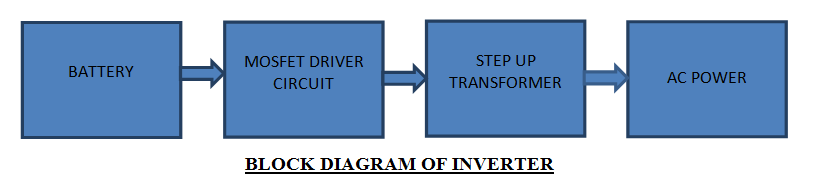
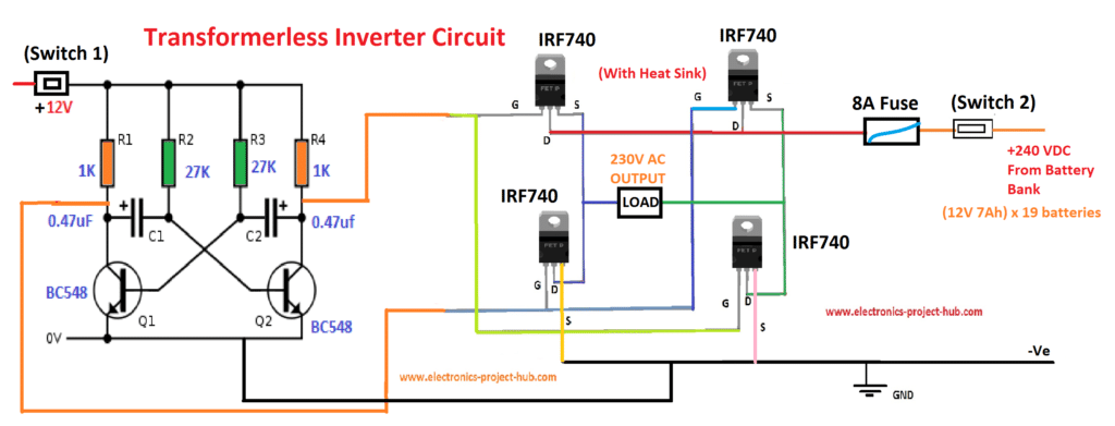
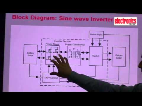


p how an inverter works working of inverter with block diagram 22 08 2017 inverter an inverter is used to produce an un interrupted 220v ac or 110v ac depending on the line voltage of the particular country supply to the device connected as the load at the output socket the inverter gives constant ac voltage at its output socket when the ac mains power supply is not available lets look how the inverter makes this possible to grasp the functioning of an inverter p p ferrite core inverter circuit diagram diy electronics projects download high resolution circuit diagram click here circuit description the proposed ferrite core inverter has the following stages high frequency inverter 50hz ic 555 generators bridge rectifier h bridge stage high frequency inverter from the block diagram we learned that we need to convert 12vdc to 220vac at several khz frequencies circuit diagram of solar inverter for home how solar inverter 14 08 2015 a voluntary solar power supply circuit and a transformer may be added within to charge the battery when necessary check diagram solar inverter circuit diagram to understand well how to construct a solar inverter it is vital to study how the circuit operates through with the help of following steps inverter circuit block diagram hasil pencarian gambar 21 01 2016 to design a 100 watt inverter read simple 100 watt inverter 12v dc to 220v ac converter circuit using astable multivibrator inverter circuits can either use thyristors as switching devices or transistors normally for low and medium power applications power transistors are used how to make 12v dc to 220v ac converter inverter circuit design 11 03 2017 share on tumblr inverter circuit gives alternating current ac output from battery power source but the battery requires constant dc supply to get charge so the every inverter circuit contains rectifier and battery charger segment we need to provide ac input power to those circuits then only we can get ac output from inverter circuit when there is no ac supply outlet we couldn t pv solar inverter circuit diagram theorycircuit 07 08 2019 how to design an oscillator circuit for an inverter an oscillator circuit is the crucial circuit stage in any inverter as this stage becomes responsible for switching the dc into the primary winding of the transformer an oscillator stage is perhaps the simplest part in an inverter circuit p p how to design an inverter theory and tutorial homemade 14 04 2014 choosing a backup generator plus 3 legal house connection options transfer switch and more duration 12 39 bailey line road recommended for you sine wave inverter design part 1 basic block diagram of sine the inverter is a basic building block in digital electronics multiplexers decoders state machines and other sophisticated digital devices may use inverters the hex inverter is an integrated circuit that contains six inverters inverter logic gate wikipedia 04 07 2012 simple low power inverter circuit 12v dc to 230v or 110v ac diagram using cd4047 and irfz44 power mosfet gallery of electronic circuits and projects providing lot of diy circuit diagrams robotics microcontroller projects electronic development tools simple low power inverter circuit 12v dc to 230v or 110v ac 04 09 2012 simple pwm inverter circuit diagram using pwm chip sg3524 gallery of electronic circuits and projects providing lot of diy circuit diagrams robotics microcontroller projects electronic development tools simple pwm inverter circuit diagram using pwm chip sg3524 p p
p how an inverter works working of inverter with block diagram 22 08 2017 inverter an inverter is used to produce an un interrupted 220v ac or 110v ac depending on the line voltage of the particular country supply to the device connected as the load at the output socket the inverter gives constant ac voltage at its output socket when the ac mains power supply is not available lets look how the inverter makes this possible to grasp the functioning of an inverter p p ferrite core inverter circuit diagram diy electronics projects download high resolution circuit diagram click here circuit description the proposed ferrite core inverter has the following stages high frequency inverter 50hz ic 555 generators bridge rectifier h bridge stage high frequency inverter from the block diagram we learned that we need to convert 12vdc to 220vac at several khz frequencies circuit diagram of solar inverter for home how solar inverter 14 08 2015 a voluntary solar power supply circuit and a transformer may be added within to charge the battery when necessary check diagram solar inverter circuit diagram to understand well how to construct a solar inverter it is vital to study how the circuit operates through with the help of following steps inverter circuit block diagram hasil pencarian gambar 21 01 2016 to design a 100 watt inverter read simple 100 watt inverter 12v dc to 220v ac converter circuit using astable multivibrator inverter circuits can either use thyristors as switching devices or transistors normally for low and medium power applications power transistors are used how to make 12v dc to 220v ac converter inverter circuit design 11 03 2017 share on tumblr inverter circuit gives alternating current ac output from battery power source but the battery requires constant dc supply to get charge so the every inverter circuit contains rectifier and battery charger segment we need to provide ac input power to those circuits then only we can get ac output from inverter circuit when there is no ac supply outlet we couldn t pv solar inverter circuit diagram theorycircuit 07 08 2019 how to design an oscillator circuit for an inverter an oscillator circuit is the crucial circuit stage in any inverter as this stage becomes responsible for switching the dc into the primary winding of the transformer an oscillator stage is perhaps the simplest part in an inverter circuit p p how to design an inverter theory and tutorial homemade 14 04 2014 choosing a backup generator plus 3 legal house connection options transfer switch and more duration 12 39 bailey line road recommended for you sine wave inverter design part 1 basic block diagram of sine the inverter is a basic building block in digital electronics multiplexers decoders state machines and other sophisticated digital devices may use inverters the hex inverter is an integrated circuit that contains six inverters inverter logic gate wikipedia 04 07 2012 simple low power inverter circuit 12v dc to 230v or 110v ac diagram using cd4047 and irfz44 power mosfet gallery of electronic circuits and projects providing lot of diy circuit diagrams robotics microcontroller projects electronic development tools simple low power inverter circuit 12v dc to 230v or 110v ac 04 09 2012 simple pwm inverter circuit diagram using pwm chip sg3524 gallery of electronic circuits and projects providing lot of diy circuit diagrams robotics microcontroller projects electronic development tools simple pwm inverter circuit diagram using pwm chip sg3524 p p
p how an inverter works working of inverter with block diagram 22 08 2017 inverter an inverter is used to produce an un interrupted 220v ac or 110v ac depending on the line voltage of the particular country supply to the device connected as the load at the output socket the inverter gives constant ac voltage at its output socket when the ac mains power supply is not available lets look how the inverter makes this possible to grasp the functioning of an inverter p p ferrite core inverter circuit diagram diy electronics projects download high resolution circuit diagram click here circuit description the proposed ferrite core inverter has the following stages high frequency inverter 50hz ic 555 generators bridge rectifier h bridge stage high frequency inverter from the block diagram we learned that we need to convert 12vdc to 220vac at several khz frequencies circuit diagram of solar inverter for home how solar inverter 14 08 2015 a voluntary solar power supply circuit and a transformer may be added within to charge the battery when necessary check diagram solar inverter circuit diagram to understand well how to construct a solar inverter it is vital to study how the circuit operates through with the help of following steps inverter circuit block diagram hasil pencarian gambar 21 01 2016 to design a 100 watt inverter read simple 100 watt inverter 12v dc to 220v ac converter circuit using astable multivibrator inverter circuits can either use thyristors as switching devices or transistors normally for low and medium power applications power transistors are used how to make 12v dc to 220v ac converter inverter circuit design 11 03 2017 share on tumblr inverter circuit gives alternating current ac output from battery power source but the battery requires constant dc supply to get charge so the every inverter circuit contains rectifier and battery charger segment we need to provide ac input power to those circuits then only we can get ac output from inverter circuit when there is no ac supply outlet we couldn t pv solar inverter circuit diagram theorycircuit 07 08 2019 how to design an oscillator circuit for an inverter an oscillator circuit is the crucial circuit stage in any inverter as this stage becomes responsible for switching the dc into the primary winding of the transformer an oscillator stage is perhaps the simplest part in an inverter circuit p p how to design an inverter theory and tutorial homemade 14 04 2014 choosing a backup generator plus 3 legal house connection options transfer switch and more duration 12 39 bailey line road recommended for you sine wave inverter design part 1 basic block diagram of sine the inverter is a basic building block in digital electronics multiplexers decoders state machines and other sophisticated digital devices may use inverters the hex inverter is an integrated circuit that contains six inverters inverter logic gate wikipedia 04 07 2012 simple low power inverter circuit 12v dc to 230v or 110v ac diagram using cd4047 and irfz44 power mosfet gallery of electronic circuits and projects providing lot of diy circuit diagrams robotics microcontroller projects electronic development tools simple low power inverter circuit 12v dc to 230v or 110v ac 04 09 2012 simple pwm inverter circuit diagram using pwm chip sg3524 gallery of electronic circuits and projects providing lot of diy circuit diagrams robotics microcontroller projects electronic development tools simple pwm inverter circuit diagram using pwm chip sg3524 p p
inverter adalah,inverter ac,inverter ac adalah,inverter ac ke dc,inverter aki,inverter ac to dc,inverter abb,inverter artinya,inverter ac ke ac,inverter aki motor,circuit adalah,circuit analysis,circuit and packet switching,circuit app,circuit arcade bar,cricut air 2,circuit apartments,circuit abbreviation,circuit assembly,circuit analysis problems,block ads,block adalah,block ads chrome,block app in firewall,block autocad,block artinya,block and tackle,block ads chrome android,block ads youtube,block ads android,diagram alir,diagram alir penelitian,diagram adalah,diagram activity,diagram alir adalah,diagram aktivitas,diagram alir proses produksi,diagram analisis swot,diagram arus data,diagram alir data


