
2. Understanding Inverter Circuit Diagram Charger
3. Components of an Inverter Circuit Diagram Charger
- Battery: Provides the DC power source for the inverter circuit diagram charger.
- Inverter: Converts DC power into AC power.
- Charger Controller: Regulates the charging process and protects the battery.
- Transformer: Increases or decreases the voltage level.
- Rectifier: Converts AC power to DC power for charging the battery.
- Voltage Regulator: Maintains a stable output voltage.
- Circuit Protection Devices: Safeguards the inverter circuit diagram charger from electrical faults.
4. Working Principle of an Inverter Circuit Diagram Charger
5. Step-by-Step Guide to Building an Inverter Circuit Diagram Charger
- Gather all the necessary components and tools.
- Design the circuit diagram, considering the power requirements and intended use.
- Assemble the components on a suitable PCB (Printed Circuit Board).
- Connect the battery, inverter, charger controller, transformer, rectifier, voltage regulator, and circuit protection devices according to the circuit diagram.
- Double-check the connections for accuracy and secure all the components.
- Test the circuit for functionality and safety.
- Make any necessary adjustments or modifications.
- Enclose the circuit in a suitable housing, ensuring proper ventilation.
- Connect the input power source and the output load to the inverter circuit diagram charger.
- Power on the device and monitor its performance.
6. Choosing the Right Components for an Inverter Circuit Diagram Charger
- Battery: Select a battery with the capacity and voltage suitable for your application. Consider factors such as battery chemistry, ampere-hour (Ah) rating, and voltage stability.
- Inverter: Choose an inverter that can handle the required power output and has the necessary input and output voltage ratings. Consider the waveform type (sinusoidal, modified sine wave, or square wave) based on your application's sensitivity.
- Charger Controller: Look for a charger controller that provides efficient charging and offers features like overcharge protection, temperature compensation, and charging status indicators.
- Transformer: Determine the required transformer specifications based on the input and output voltage levels. Consider factors such as turns ratio, core material, and efficiency.
- Rectifier: Select a rectifier that can convert the AC power from the inverter to DC power for charging the battery. Consider the rectifier type (full wave or half wave) and its current and voltage ratings.
- Voltage Regulator: Choose a voltage regulator that can maintain a stable output voltage, preventing voltage fluctuations that could harm connected devices.
- Circuit Protection Devices: Incorporate circuit protection devices such as fuses, circuit breakers, and surge protectors to safeguard the inverter circuit diagram charger from overcurrent, short circuits, and voltage spikes.
7. Important Considerations for Designing an Inverter Circuit Diagram Charger
- Efficiency: Optimize the efficiency of the inverter circuit diagram charger to minimize energy loss during the conversion process. This helps maximize the battery's charging efficiency and overall system performance.
- Cooling and Ventilation: Ensure adequate cooling and ventilation for the inverter, transformer, and other heat-generating components to prevent overheating and ensure their longevity.
- Noise and Harmonics: Address potential issues related to electrical noise and harmonics generated by the inverter circuit diagram charger. Implement suitable filtering techniques to reduce noise and maintain power quality.
- Safety Measures: Incorporate safety features such as grounding, insulation, and protection against electrical shocks, short circuits, and overloads. Adhere to relevant safety standards and regulations.
- Scalability and Future Expansion: Design the inverter circuit diagram charger with scalability in mind, allowing for future expansion or modifications based on evolving power requirements or additional functionalities.
- Environmental Considerations: Consider environmental factors such as temperature, humidity, and dust when designing the inverter circuit diagram charger. Choose components and materials that can withstand the intended operating conditions.
8. Safety Precautions for Using an Inverter Circuit Diagram Charger
- Read the User Manual: Familiarize yourself with the user manual provided by the manufacturer to understand the specific safety instructions and operational guidelines.
- Proper Installation: Install the inverter circuit diagram charger in a well-ventilated area, away from flammable materials, water sources, and direct sunlight. Follow the installation instructions carefully to prevent accidents or damage.
- Grounding: Ensure proper grounding of the inverter circuit diagram charger to minimize the risk of electrical shocks and ensure the safety of connected devices.
- Battery Safety: Handle batteries with caution, following the manufacturer's guidelines. Avoid short circuits, overcharging, and exposure to extreme temperatures.
- Maintenance: Regularly inspect and maintain the inverter circuit diagram charger. Check for loose connections, signs of damage, or abnormal behavior. Perform maintenance tasks as recommended by the manufacturer.
- Overload Protection: Avoid overloading the inverter circuit diagram charger beyond its rated capacity. Overloading can lead to overheating, reduced efficiency, and potential component failure.
- Ventilation: Ensure proper ventilation around the inverter circuit diagram charger to dissipate heat effectively. Blocked ventilation can result in overheating and reduced performance.
- Electrical Safety: Take precautions when working with electrical connections. Ensure the power source is turned off before making any adjustments or repairs.
- Surge Protection: Consider using surge protectors to safeguard the inverter circuit diagram charger and connected devices from power surges or voltage spikes.
- Fire Safety: Keep fire extinguishers readily available in case of emergencies. Avoid placing flammable materials near the inverter circuit diagram charger.
9. Advantages of an Inverter Circuit Diagram Charger
- Dual Functionality: The inverter circuit diagram charger combines the functions of an inverter and a battery charger in a single device, providing convenience and cost-effectiveness.
- Portable Power: With an inverter circuit diagram charger, you can have access to AC power even in remote locations where grid power is unavailable. It enables you to run electronic devices and charge batteries on the go.
- Backup Power: Inverter circuit diagram chargers serve as excellent backup power solutions during power outages. They can keep essential devices operational and ensure uninterrupted power supply.
- Renewable Energy Integration: Inverter circuit diagram chargers facilitate the integration of renewable energy sources such as solar panels or wind turbines. They convert the DC power generated by these sources into usable AC power while simultaneously charging batteries.
- Efficient Charging: The charger controller in the inverter circuit diagram charger optimizes the charging process, ensuring efficient and safe charging of batteries, thus extending their lifespan.
- Versatility: Inverter circuit diagram chargers can be used in various applications, including recreational vehicles, boats, off-grid cabins, emergency power systems, and portable electronics.
10. Limitations of an Inverter Circuit Diagram Charger
- Power Limitations: Inverter circuit diagram chargers have a maximum power output capacity. Exceeding this capacity can lead to decreased efficiency, voltage fluctuations, or even equipment failure.
- Battery Compatibility: The inverter circuit diagram charger should be compatible with the battery type and voltage. Using incompatible batteries can result in improper charging or damage to the battery.
- Charging Time: The charging time of batteries using an inverter circuit diagram charger depends on factors such as battery capacity, charger rating, and available charging current. It's essential to consider the charging time when planning power usage.
- Efficiency Trade-Off: The conversion of DC power to AC power and the charging process involve energy losses. While modern inverter circuit diagram chargers have improved efficiency, there is still some energy loss during the conversion process.
11. Applications of an Inverter Circuit Diagram Charger
- Off-Grid Systems: Inverter circuit diagram chargers are commonly used in off-grid solar power systems, where they convert DC power from solar panels into AC power for household use while charging batteries for nighttime or low-sunlight periods.
- Recreational Vehicles (RVs): Inverter circuit diagram chargers are used in RVs to provide AC power for appliances, lighting, and entertainment systems. They also charge the onboard batteries while connected to shore power or running the vehicle's engine.
- Emergency Power Systems: Inverter circuit diagram chargers play a crucial role in emergency power systems, providing backup power during power outages. They ensure continuous operation of essential devices such as lights, communication equipment, and medical devices.
- Marine Applications: Inverter circuit diagram chargers are used in boats and yachts to power various appliances and electronics, including navigation systems, refrigerators, and entertainment devices. They can also charge batteries while connected to shore power or running the boat's engine.
- Remote Locations: Inverter circuit diagram chargers are valuable in remote locations where access to grid power is limited. They allow individuals to have access to AC power for various purposes such as lighting, communication, and running small appliances.
- Portable Electronics: Inverter circuit diagram chargers can be used to power and charge portable electronic devices such as laptops, smartphones, tablets, and cameras. This makes them ideal for outdoor activities, camping, or travel.
12. Troubleshooting Common Issues with an Inverter Circuit Diagram Charger
- No Output Power: Check the battery connections and ensure they are secure. Verify that the battery has sufficient charge. Inspect the inverter and charger controller for any faults or error indicators.
- Overheating: Ensure proper ventilation around the inverter circuit diagram charger. Clean any accumulated dust or debris that may be blocking the airflow. If the problem persists, consider reducing the load on the inverter or upgrading to a higher-capacity model.
- Battery Not Charging: Check the battery voltage and ensure it is within the charger's acceptable range. Inspect the charger controller for any error indicators or misconfigurations. Verify that the charger is receiving the correct input voltage.
- Voltage Fluctuations: If you notice voltage fluctuations in the AC output, check the input power source for stability. Ensure the inverter circuit diagram charger is not overloaded and that the connected devices are compatible with the inverter's waveform type.
- Abnormal Noise or Smell: If you detect unusual noises or odors coming from the inverter circuit diagram charger, immediately disconnect the power source and inspect for any visible damage or signs of overheating. Consult a professional if necessary.
- Remember, troubleshooting steps may vary depending on the specific model and manufacturer guidelines. Always refer to the user manual or seek professional assistance when dealing with complex issues.
Conclusion
inverter circuit diagram charger


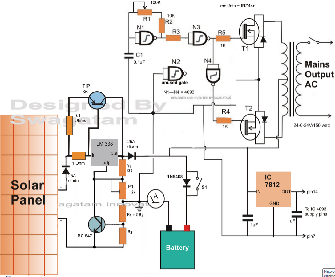
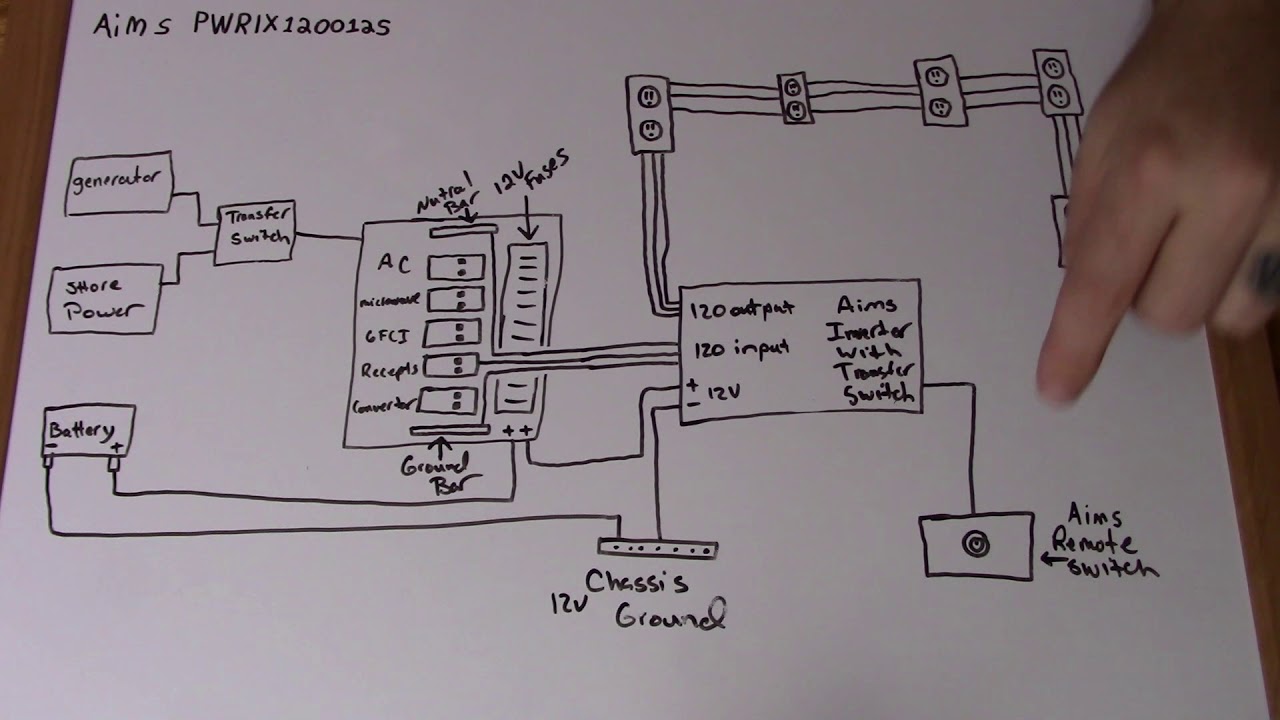


p inverter battery charger circuit many circuits 22 05 2017 inverter battery charger circuit battery charger circuit sg3524 battery charger circuit float charger circuit many circuits this is an electronic circuit sharing and tutorial blog which offers designed and tested circuits for free p p 500 watt inverter circuit with battery charger homemade circuit 30 11 2019 to keep the design simple yet effective i have avoided the use an automatic cut off for the battery charger here and have also ensured a single common transformer is used for the inverter and the charger operations the complete circuit diagram for the proposed 500 watt inverter with battery charger can be seen below rv inverter charger wiring diagram free wiring diagram collection of rv inverter charger wiring diagram a wiring diagram is a simplified conventional photographic representation of an electrical circuit it shows the components of the circuit as simplified shapes and the power as well as signal connections between the devices inverter circuit diagram charger hasil pencarian gambar here is the circuit diagram of a simple 100 watt inverter using ic cd4047 and mosfet irf540 application report sprabt0 january 2013 1 grid connected micro solar inverter implement using a c2000 mcu jason tao vieri xue mcu dmcdps sae team solar panel inverter circuit diagram circuit diagram images 11 03 2017 share on tumblr inverter circuit gives alternating current ac output from battery power source but the battery requires constant dc supply to get charge so the every inverter circuit contains rectifier and battery charger segment we need to provide ac input power to those circuits then only we can get ac output from inverter circuit when there is no ac supply outlet we couldn t pv solar inverter circuit diagram theorycircuit assortment of marine inverter charger wiring diagram a wiring diagram is a streamlined traditional photographic representation of an electric circuit p p marine inverter charger wiring diagram free wiring diagram this is the circuit diagram of car battery charger which used scr 2n3896 if the circuit built and setup correctly it will safely charge at 10 amps and automatically regulate down to a trickle charge inverter circuit and products 04 01 2020 inverter circuits being the favorites with these devices we would be discussing one such design incorporating mosfets for powering the output stage of the circuit referring to the diagram we see a very basic inverter design involving a square wave oscillator stage a buffer stage and the power output stage 7 simple inverter circuits you can build at home homemade this is the circuit diagram of car battery charger which used scr 2n3896 if the circuit built and setup correctly it will safely charge at 10 amps and automatically regulate down to a trickle charge this charger can t be used as a power supply without having a battery in place the battery must be connected to get power out car battery charger based scr 2n3896 inverter circuit and circuit diagram of automatic battery charger this automatic battery charger circuit is mainly involves two sections power supply section and load comparison section the main supply voltage 230v 50hz is connected to the primary winding of the center tapped transformer to step down the voltage to 15 0 15v automatic 12v portable battery charger circuit using lm317 p p charger inverter charger inverter inverter charger search inverter charger a charger search a charger
p inverter battery charger circuit many circuits 22 05 2017 inverter battery charger circuit battery charger circuit sg3524 battery charger circuit float charger circuit many circuits this is an electronic circuit sharing and tutorial blog which offers designed and tested circuits for free p p 500 watt inverter circuit with battery charger homemade circuit 30 11 2019 to keep the design simple yet effective i have avoided the use an automatic cut off for the battery charger here and have also ensured a single common transformer is used for the inverter and the charger operations the complete circuit diagram for the proposed 500 watt inverter with battery charger can be seen below rv inverter charger wiring diagram free wiring diagram collection of rv inverter charger wiring diagram a wiring diagram is a simplified conventional photographic representation of an electrical circuit it shows the components of the circuit as simplified shapes and the power as well as signal connections between the devices inverter circuit diagram charger hasil pencarian gambar here is the circuit diagram of a simple 100 watt inverter using ic cd4047 and mosfet irf540 application report sprabt0 january 2013 1 grid connected micro solar inverter implement using a c2000 mcu jason tao vieri xue mcu dmcdps sae team solar panel inverter circuit diagram circuit diagram images 11 03 2017 share on tumblr inverter circuit gives alternating current ac output from battery power source but the battery requires constant dc supply to get charge so the every inverter circuit contains rectifier and battery charger segment we need to provide ac input power to those circuits then only we can get ac output from inverter circuit when there is no ac supply outlet we couldn t pv solar inverter circuit diagram theorycircuit assortment of marine inverter charger wiring diagram a wiring diagram is a streamlined traditional photographic representation of an electric circuit p p marine inverter charger wiring diagram free wiring diagram this is the circuit diagram of car battery charger which used scr 2n3896 if the circuit built and setup correctly it will safely charge at 10 amps and automatically regulate down to a trickle charge inverter circuit and products 04 01 2020 inverter circuits being the favorites with these devices we would be discussing one such design incorporating mosfets for powering the output stage of the circuit referring to the diagram we see a very basic inverter design involving a square wave oscillator stage a buffer stage and the power output stage 7 simple inverter circuits you can build at home homemade this is the circuit diagram of car battery charger which used scr 2n3896 if the circuit built and setup correctly it will safely charge at 10 amps and automatically regulate down to a trickle charge this charger can t be used as a power supply without having a battery in place the battery must be connected to get power out car battery charger based scr 2n3896 inverter circuit and circuit diagram of automatic battery charger this automatic battery charger circuit is mainly involves two sections power supply section and load comparison section the main supply voltage 230v 50hz is connected to the primary winding of the center tapped transformer to step down the voltage to 15 0 15v automatic 12v portable battery charger circuit using lm317 p p charger inverter charger inverter inverter charger search inverter charger a charger search a charger
p inverter battery charger circuit many circuits 22 05 2017 inverter battery charger circuit battery charger circuit sg3524 battery charger circuit float charger circuit many circuits this is an electronic circuit sharing and tutorial blog which offers designed and tested circuits for free p p 500 watt inverter circuit with battery charger homemade circuit 30 11 2019 to keep the design simple yet effective i have avoided the use an automatic cut off for the battery charger here and have also ensured a single common transformer is used for the inverter and the charger operations the complete circuit diagram for the proposed 500 watt inverter with battery charger can be seen below rv inverter charger wiring diagram free wiring diagram collection of rv inverter charger wiring diagram a wiring diagram is a simplified conventional photographic representation of an electrical circuit it shows the components of the circuit as simplified shapes and the power as well as signal connections between the devices inverter circuit diagram charger hasil pencarian gambar here is the circuit diagram of a simple 100 watt inverter using ic cd4047 and mosfet irf540 application report sprabt0 january 2013 1 grid connected micro solar inverter implement using a c2000 mcu jason tao vieri xue mcu dmcdps sae team solar panel inverter circuit diagram circuit diagram images 11 03 2017 share on tumblr inverter circuit gives alternating current ac output from battery power source but the battery requires constant dc supply to get charge so the every inverter circuit contains rectifier and battery charger segment we need to provide ac input power to those circuits then only we can get ac output from inverter circuit when there is no ac supply outlet we couldn t pv solar inverter circuit diagram theorycircuit assortment of marine inverter charger wiring diagram a wiring diagram is a streamlined traditional photographic representation of an electric circuit p p marine inverter charger wiring diagram free wiring diagram this is the circuit diagram of car battery charger which used scr 2n3896 if the circuit built and setup correctly it will safely charge at 10 amps and automatically regulate down to a trickle charge inverter circuit and products 04 01 2020 inverter circuits being the favorites with these devices we would be discussing one such design incorporating mosfets for powering the output stage of the circuit referring to the diagram we see a very basic inverter design involving a square wave oscillator stage a buffer stage and the power output stage 7 simple inverter circuits you can build at home homemade this is the circuit diagram of car battery charger which used scr 2n3896 if the circuit built and setup correctly it will safely charge at 10 amps and automatically regulate down to a trickle charge this charger can t be used as a power supply without having a battery in place the battery must be connected to get power out car battery charger based scr 2n3896 inverter circuit and circuit diagram of automatic battery charger this automatic battery charger circuit is mainly involves two sections power supply section and load comparison section the main supply voltage 230v 50hz is connected to the primary winding of the center tapped transformer to step down the voltage to 15 0 15v automatic 12v portable battery charger circuit using lm317 p p charger inverter charger inverter inverter charger search inverter charger a charger search a charger
inverter adalah,inverter ac,inverter ac adalah,inverter ac ke dc,inverter aki,inverter ac to dc,inverter abb,inverter artinya,inverter ac ke ac,inverter aki motor,circuit adalah,circuit analysis,circuit and packet switching,circuit app,circuit arcade bar,cricut air 2,circuit apartments,circuit abbreviation,circuit assembly,circuit analysis problems,diagram alir,diagram alir penelitian,diagram adalah,diagram activity,diagram alir adalah,diagram aktivitas,diagram alir proses produksi,diagram analisis swot,diagram arus data,diagram alir data,charger aki,charger aki mobil,charger asus,charger aki motor,charger asus laptop,charger aukey,charger anker,charger apple watch,charger aki otomatis,charger acer


