1000w inverter circuit diagram with pcb layout

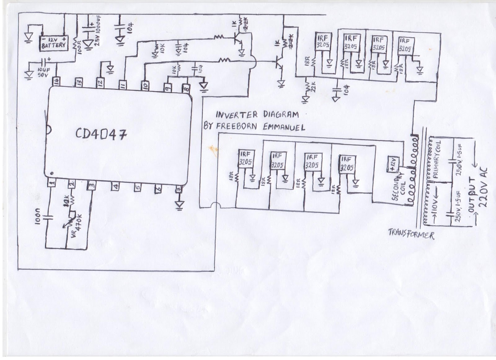

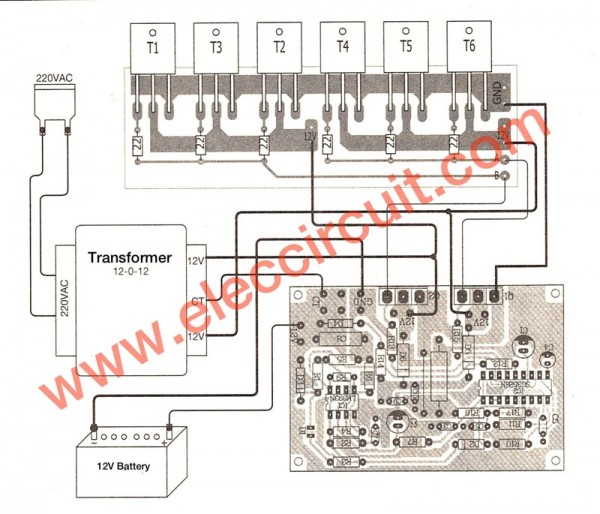


p 1000w power inverter electronic circuit diagram schematic 1000w power inverter circuit diagram this is the power inverter circuit based mosfet rfp50n06 the inverter capable to handle loads up to 1000w it s depended on your power inverter transformer the rfp50n06 fets are rated at 50 amps and 60 volts heatsink is required for cooling the mosfets p p 100w transistored inverter circuit diagram with pcb layout inverter diagram the q1 and q2 used generate square wave q5 q8 amplify the signal and the transformer to increase the ac square wave current from 12vac to 220v ac 50hz inverter pcb layout the following image is the bottom copper pcb layout and to layout for the components placement you may use universal pcb veroboard to make it easier 1000w power inverter circuit scheme 1000w power inverter circuit diagram this is the power inverter circuit based mosfet rfp50n06 the inverter capable to handle loads up to 1000w it s depended on your power inverter transformer the rfp50n06 fets are rated at 50 amps and 60 volts heatsink is required for cooling the mosfets 1000w inverter circuit diagram with pcb layout hasil pencarian gambar 23 09 2016 here are limitations i get had numerous desires in favor of an inverter for 1000 watts and even supplementary regretful i don t feel this is sound by 1000 watts and operating from a 12 volt source the input current wish befall close to 100 amps with the intention of would require a hugh size of a primary wire 1000w mosfet power inverter circuit electronic circuit this schematic diagram come from circuit 1000w power inverter go to that page to read the explanation about above circuit design in the electrical sector a schematic diagram is usually used to describe the design or model of equipment 1000w power inverter pcb layout design circuit schematic 1000w power inverter circuit diagram this is the power inverter circuit based mosfet rfp50n06 the inverter capable to handle loads up to 1000w it s depended on your power inverter transformer the rfp50n06 fets are rated at 50 amps and 60 volts heatsink is required for cooling the mosfets p p 1000w power inverter electronic schematic diagram 300watt inverter circut inverter circuit diagram 1000w inverter pcb circuit layout circuit diagram for charging 12 voltage z44 inverter circuit 100watts inverter using e33 transformer car battery diode power inverter with mosfet irf 260 mosfet z44 inverter circuit diagram tip35c circuit inverter diagram archives inverter circuit and products 300watt inverter circuit diagram pcb layout design and component placement 300watt inverter circuit diagram pcb layout electronic circuit 300watt inverter circut inverter circuit diagram 1000w inverter pcb circuit layout circuit diagram for charging 12 voltage z44 inverter circuit 100watts inverter using e33 transformer car battery diode power inverter with mosfet irf 260 mosfet z44 inverter circuit diagram tip35c circuit 3000w power inverter 12v to 230v inverter circuit and products the circute i post is just a simple dc ac inverter circute diagram protections are not included in the diagram the circute contain only oscilator which is sg3524 it only generate 50hz clock pulse which is out of phase with the other pin 14 and 11 the signal passes through a biasing resistor r2 and r4 r3 and r5 serve as pull down resistor the mosfet drive your 12v 50hz signal into your step up 1000w dc ac inverter circuit diagram forum for electronics p p inverter 1000w search inverter 1000w
p 1000w power inverter electronic circuit diagram schematic 1000w power inverter circuit diagram this is the power inverter circuit based mosfet rfp50n06 the inverter capable to handle loads up to 1000w it s depended on your power inverter transformer the rfp50n06 fets are rated at 50 amps and 60 volts heatsink is required for cooling the mosfets p p 100w transistored inverter circuit diagram with pcb layout inverter diagram the q1 and q2 used generate square wave q5 q8 amplify the signal and the transformer to increase the ac square wave current from 12vac to 220v ac 50hz inverter pcb layout the following image is the bottom copper pcb layout and to layout for the components placement you may use universal pcb veroboard to make it easier 1000w power inverter circuit scheme 1000w power inverter circuit diagram this is the power inverter circuit based mosfet rfp50n06 the inverter capable to handle loads up to 1000w it s depended on your power inverter transformer the rfp50n06 fets are rated at 50 amps and 60 volts heatsink is required for cooling the mosfets 1000w inverter circuit diagram with pcb layout hasil pencarian gambar 23 09 2016 here are limitations i get had numerous desires in favor of an inverter for 1000 watts and even supplementary regretful i don t feel this is sound by 1000 watts and operating from a 12 volt source the input current wish befall close to 100 amps with the intention of would require a hugh size of a primary wire 1000w mosfet power inverter circuit electronic circuit this schematic diagram come from circuit 1000w power inverter go to that page to read the explanation about above circuit design in the electrical sector a schematic diagram is usually used to describe the design or model of equipment 1000w power inverter pcb layout design circuit schematic 1000w power inverter circuit diagram this is the power inverter circuit based mosfet rfp50n06 the inverter capable to handle loads up to 1000w it s depended on your power inverter transformer the rfp50n06 fets are rated at 50 amps and 60 volts heatsink is required for cooling the mosfets p p 1000w power inverter electronic schematic diagram 300watt inverter circut inverter circuit diagram 1000w inverter pcb circuit layout circuit diagram for charging 12 voltage z44 inverter circuit 100watts inverter using e33 transformer car battery diode power inverter with mosfet irf 260 mosfet z44 inverter circuit diagram tip35c circuit inverter diagram archives inverter circuit and products 300watt inverter circuit diagram pcb layout design and component placement 300watt inverter circuit diagram pcb layout electronic circuit 300watt inverter circut inverter circuit diagram 1000w inverter pcb circuit layout circuit diagram for charging 12 voltage z44 inverter circuit 100watts inverter using e33 transformer car battery diode power inverter with mosfet irf 260 mosfet z44 inverter circuit diagram tip35c circuit 3000w power inverter 12v to 230v inverter circuit and products the circute i post is just a simple dc ac inverter circute diagram protections are not included in the diagram the circute contain only oscilator which is sg3524 it only generate 50hz clock pulse which is out of phase with the other pin 14 and 11 the signal passes through a biasing resistor r2 and r4 r3 and r5 serve as pull down resistor the mosfet drive your 12v 50hz signal into your step up 1000w dc ac inverter circuit diagram forum for electronics p p inverter 1000w search inverter 1000w
p 1000w power inverter electronic circuit diagram schematic 1000w power inverter circuit diagram this is the power inverter circuit based mosfet rfp50n06 the inverter capable to handle loads up to 1000w it s depended on your power inverter transformer the rfp50n06 fets are rated at 50 amps and 60 volts heatsink is required for cooling the mosfets p p 100w transistored inverter circuit diagram with pcb layout inverter diagram the q1 and q2 used generate square wave q5 q8 amplify the signal and the transformer to increase the ac square wave current from 12vac to 220v ac 50hz inverter pcb layout the following image is the bottom copper pcb layout and to layout for the components placement you may use universal pcb veroboard to make it easier 1000w power inverter circuit scheme 1000w power inverter circuit diagram this is the power inverter circuit based mosfet rfp50n06 the inverter capable to handle loads up to 1000w it s depended on your power inverter transformer the rfp50n06 fets are rated at 50 amps and 60 volts heatsink is required for cooling the mosfets 1000w inverter circuit diagram with pcb layout hasil pencarian gambar 23 09 2016 here are limitations i get had numerous desires in favor of an inverter for 1000 watts and even supplementary regretful i don t feel this is sound by 1000 watts and operating from a 12 volt source the input current wish befall close to 100 amps with the intention of would require a hugh size of a primary wire 1000w mosfet power inverter circuit electronic circuit this schematic diagram come from circuit 1000w power inverter go to that page to read the explanation about above circuit design in the electrical sector a schematic diagram is usually used to describe the design or model of equipment 1000w power inverter pcb layout design circuit schematic 1000w power inverter circuit diagram this is the power inverter circuit based mosfet rfp50n06 the inverter capable to handle loads up to 1000w it s depended on your power inverter transformer the rfp50n06 fets are rated at 50 amps and 60 volts heatsink is required for cooling the mosfets p p 1000w power inverter electronic schematic diagram 300watt inverter circut inverter circuit diagram 1000w inverter pcb circuit layout circuit diagram for charging 12 voltage z44 inverter circuit 100watts inverter using e33 transformer car battery diode power inverter with mosfet irf 260 mosfet z44 inverter circuit diagram tip35c circuit inverter diagram archives inverter circuit and products 300watt inverter circuit diagram pcb layout design and component placement 300watt inverter circuit diagram pcb layout electronic circuit 300watt inverter circut inverter circuit diagram 1000w inverter pcb circuit layout circuit diagram for charging 12 voltage z44 inverter circuit 100watts inverter using e33 transformer car battery diode power inverter with mosfet irf 260 mosfet z44 inverter circuit diagram tip35c circuit 3000w power inverter 12v to 230v inverter circuit and products the circute i post is just a simple dc ac inverter circute diagram protections are not included in the diagram the circute contain only oscilator which is sg3524 it only generate 50hz clock pulse which is out of phase with the other pin 14 and 11 the signal passes through a biasing resistor r2 and r4 r3 and r5 serve as pull down resistor the mosfet drive your 12v 50hz signal into your step up 1000w dc ac inverter circuit diagram forum for electronics p p inverter 1000w search inverter 1000w
1000w amplifier,1000w amp,1000w amplifier board,1000w aquarium heater,1000w amplifier circuit diagram,1000w atv,1000w amp wiring kit,1000w active speakers,1000w air conditioner,1000w amp kit,inverter adalah,inverter ac,inverter ac adalah,inverter ac ke dc,inverter aki,inverter ac to dc,inverter abb,inverter artinya,inverter ac ke ac,inverter aki motor,circuit adalah,circuit analysis,circuit and packet switching,circuit app,circuit arcade bar,cricut air 2,circuit apartments,circuit abbreviation,circuit assembly,circuit analysis problems,diagram alir,diagram alir penelitian,diagram adalah,diagram activity,diagram alir adalah,diagram aktivitas,diagram alir proses produksi,diagram analisis swot,diagram arus data,diagram alir data,with all i am,with all i am lyrics,with artinya,with all i am chord,with all due respect,with arms wide open,with a grain of salt,with all due respect meaning,with all my heart,with a little help from my friends lyrics,pcb adalah,pcb ac,pcb ac daikin,pcb ac lg,pcb amplifier,pcb assembly,pcb ac sharp,pcb artinya,pcb ac panasonic,pcb ac samsung,layout adalah,layout android,layout apk,layout autocad,layout artinya,layout apartemen,layout apotek,layout app,layout amplop,layout acara


