inverter circuit diagram transistor
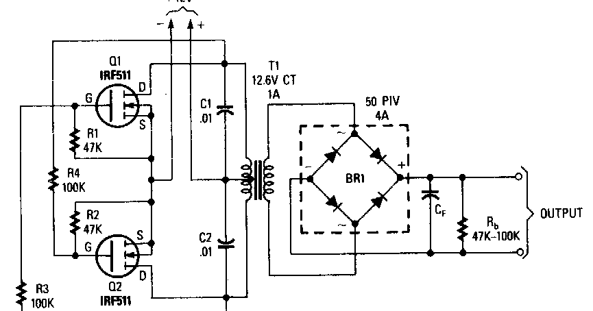
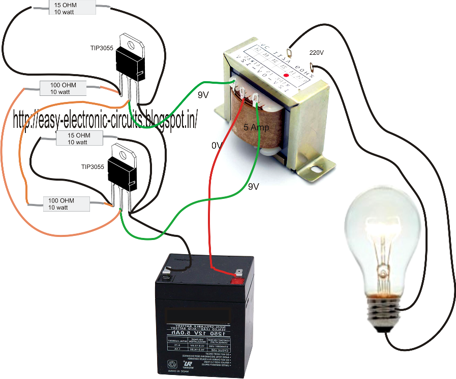
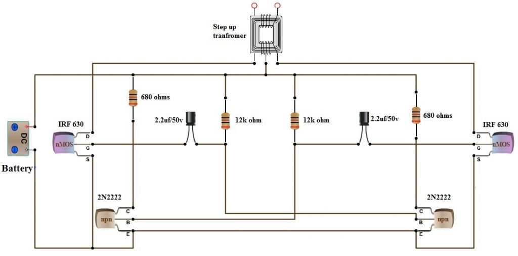
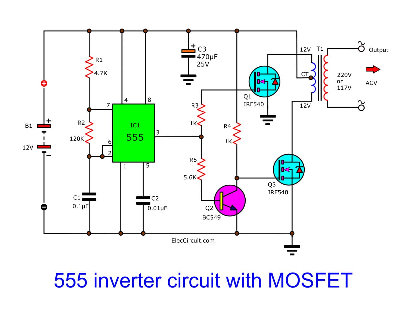


p electronics club transistor circuits functional model base inverters not gates are available on logic ics but if you only require one inverter it may be better to use this simple transistor circuit the output signal voltage is the inverse of the input signal when the input is high vs the output is low 0v when the input is low 0v the output is high vs p p inverter circuit and products this is the scheme diagram of 500w power inverter circuit which build using 10 pieces of well known npn power transistor 2n3055 to amplify the ac signal produced by multivibrator the frequency generator multivibrator is built based on transistors too inverter circuit 500w 12v to 220v eleccircuit com 13 10 2019 hm i already made this circuit inverter and i read some questions that need help the resistor w out wattage is all 1 4 watt cfr and the 1n414b you may use 1n4148 for fast switching and also the diode dx2a it means its a diode you may use 1n5402 and to be able to have an output fix to 500 watt the transistor should be 14 pc s and it means 7 channel bec the 1st stage of 2n3055 is just to inverter circuit diagram transistor hasil pencarian gambar how to build an inverter with a transistor in this circuit we will build an inverter with a transistor an inverter is a component or device that inverts the state or logic level of a signal to the opposite logic level thus if a low signal is fed into an inverter it flips it to a high isgnal how to build an inverter with a transistor 500 watt inverter using mosfet battery full charge indicator circuit diagram dosto jaisa ki aap sabhi jante hai ki maine 500 watt inverter circuit board local market se puchase kiya tha isliye aaplogo ko inverter ka circuit diagram dene me mujhe pareshani aa rahi thi lekin ab maine ye inverter circuit diagram bana liya hai to aap sabhi is circuit diagram ka use kar ke khud ka inverter bana 500 watt inverter circuit diagram using mosfet grow amis an inverter circuit outputs a voltage representing the opposite logic level to its input its main function is to invert the input signal applied if the applied input is low then the output becomes high and vice versa inverters can be constructed using a single nmos transistor or a single pmos transistor coupled with a resistor since this p p inverter logic gate wikipedia 21 01 2016 to design a 100 watt inverter read simple 100 watt inverter 12v dc to 220v ac converter circuit using astable multivibrator inverter circuits can either use thyristors as switching devices or transistors normally for low and medium power applications power transistors are used how to make 12v dc to 220v ac converter inverter circuit design 04 01 2020 inverter circuits being the favorites with these devices we would be discussing one such design incorporating mosfets for powering the output stage of the circuit referring to the diagram we see a very basic inverter design involving a square wave oscillator stage a buffer stage and the power output stage 7 simple inverter circuits you can build at home homemade above scheme diagram is the circuit diagram of low budget easy built low power power inverter designed using ic 556 as multivibrator and transistor tip120 to amplify the signal from multivibrator 100w inverter 12v to 220v inverter diagram archives inverter circuit and products the circuit demonstrates the use of a transistor as a inverter the output of an inverter is the opposite of its input when the input is logical 1 the output is logical 0 in this example circuit the input is a push button switch and the output is an led light when the switch is open or off the led is on npn transistor inverter circuit sully station technologies p p on transistor search on transistor find components on octopart transistor
p electronics club transistor circuits functional model base inverters not gates are available on logic ics but if you only require one inverter it may be better to use this simple transistor circuit the output signal voltage is the inverse of the input signal when the input is high vs the output is low 0v when the input is low 0v the output is high vs p p inverter circuit and products this is the scheme diagram of 500w power inverter circuit which build using 10 pieces of well known npn power transistor 2n3055 to amplify the ac signal produced by multivibrator the frequency generator multivibrator is built based on transistors too inverter circuit 500w 12v to 220v eleccircuit com 13 10 2019 hm i already made this circuit inverter and i read some questions that need help the resistor w out wattage is all 1 4 watt cfr and the 1n414b you may use 1n4148 for fast switching and also the diode dx2a it means its a diode you may use 1n5402 and to be able to have an output fix to 500 watt the transistor should be 14 pc s and it means 7 channel bec the 1st stage of 2n3055 is just to inverter circuit diagram transistor hasil pencarian gambar how to build an inverter with a transistor in this circuit we will build an inverter with a transistor an inverter is a component or device that inverts the state or logic level of a signal to the opposite logic level thus if a low signal is fed into an inverter it flips it to a high isgnal how to build an inverter with a transistor 500 watt inverter using mosfet battery full charge indicator circuit diagram dosto jaisa ki aap sabhi jante hai ki maine 500 watt inverter circuit board local market se puchase kiya tha isliye aaplogo ko inverter ka circuit diagram dene me mujhe pareshani aa rahi thi lekin ab maine ye inverter circuit diagram bana liya hai to aap sabhi is circuit diagram ka use kar ke khud ka inverter bana 500 watt inverter circuit diagram using mosfet grow amis an inverter circuit outputs a voltage representing the opposite logic level to its input its main function is to invert the input signal applied if the applied input is low then the output becomes high and vice versa inverters can be constructed using a single nmos transistor or a single pmos transistor coupled with a resistor since this p p inverter logic gate wikipedia 21 01 2016 to design a 100 watt inverter read simple 100 watt inverter 12v dc to 220v ac converter circuit using astable multivibrator inverter circuits can either use thyristors as switching devices or transistors normally for low and medium power applications power transistors are used how to make 12v dc to 220v ac converter inverter circuit design 04 01 2020 inverter circuits being the favorites with these devices we would be discussing one such design incorporating mosfets for powering the output stage of the circuit referring to the diagram we see a very basic inverter design involving a square wave oscillator stage a buffer stage and the power output stage 7 simple inverter circuits you can build at home homemade above scheme diagram is the circuit diagram of low budget easy built low power power inverter designed using ic 556 as multivibrator and transistor tip120 to amplify the signal from multivibrator 100w inverter 12v to 220v inverter diagram archives inverter circuit and products the circuit demonstrates the use of a transistor as a inverter the output of an inverter is the opposite of its input when the input is logical 1 the output is logical 0 in this example circuit the input is a push button switch and the output is an led light when the switch is open or off the led is on npn transistor inverter circuit sully station technologies p p on transistor search on transistor find components on octopart transistor
p electronics club transistor circuits functional model base inverters not gates are available on logic ics but if you only require one inverter it may be better to use this simple transistor circuit the output signal voltage is the inverse of the input signal when the input is high vs the output is low 0v when the input is low 0v the output is high vs p p inverter circuit and products this is the scheme diagram of 500w power inverter circuit which build using 10 pieces of well known npn power transistor 2n3055 to amplify the ac signal produced by multivibrator the frequency generator multivibrator is built based on transistors too inverter circuit 500w 12v to 220v eleccircuit com 13 10 2019 hm i already made this circuit inverter and i read some questions that need help the resistor w out wattage is all 1 4 watt cfr and the 1n414b you may use 1n4148 for fast switching and also the diode dx2a it means its a diode you may use 1n5402 and to be able to have an output fix to 500 watt the transistor should be 14 pc s and it means 7 channel bec the 1st stage of 2n3055 is just to inverter circuit diagram transistor hasil pencarian gambar how to build an inverter with a transistor in this circuit we will build an inverter with a transistor an inverter is a component or device that inverts the state or logic level of a signal to the opposite logic level thus if a low signal is fed into an inverter it flips it to a high isgnal how to build an inverter with a transistor 500 watt inverter using mosfet battery full charge indicator circuit diagram dosto jaisa ki aap sabhi jante hai ki maine 500 watt inverter circuit board local market se puchase kiya tha isliye aaplogo ko inverter ka circuit diagram dene me mujhe pareshani aa rahi thi lekin ab maine ye inverter circuit diagram bana liya hai to aap sabhi is circuit diagram ka use kar ke khud ka inverter bana 500 watt inverter circuit diagram using mosfet grow amis an inverter circuit outputs a voltage representing the opposite logic level to its input its main function is to invert the input signal applied if the applied input is low then the output becomes high and vice versa inverters can be constructed using a single nmos transistor or a single pmos transistor coupled with a resistor since this p p inverter logic gate wikipedia 21 01 2016 to design a 100 watt inverter read simple 100 watt inverter 12v dc to 220v ac converter circuit using astable multivibrator inverter circuits can either use thyristors as switching devices or transistors normally for low and medium power applications power transistors are used how to make 12v dc to 220v ac converter inverter circuit design 04 01 2020 inverter circuits being the favorites with these devices we would be discussing one such design incorporating mosfets for powering the output stage of the circuit referring to the diagram we see a very basic inverter design involving a square wave oscillator stage a buffer stage and the power output stage 7 simple inverter circuits you can build at home homemade above scheme diagram is the circuit diagram of low budget easy built low power power inverter designed using ic 556 as multivibrator and transistor tip120 to amplify the signal from multivibrator 100w inverter 12v to 220v inverter diagram archives inverter circuit and products the circuit demonstrates the use of a transistor as a inverter the output of an inverter is the opposite of its input when the input is logical 1 the output is logical 0 in this example circuit the input is a push button switch and the output is an led light when the switch is open or off the led is on npn transistor inverter circuit sully station technologies p p on transistor search on transistor find components on octopart transistor
inverter adalah,inverter ac,inverter ac adalah,inverter ac ke dc,inverter aki,inverter ac to dc,inverter abb,inverter artinya,inverter ac ke ac,inverter aki motor,circuit adalah,circuit analysis,circuit and packet switching,circuit app,circuit arcade bar,cricut air 2,circuit apartments,circuit abbreviation,circuit assembly,circuit analysis problems,diagram alir,diagram alir penelitian,diagram adalah,diagram activity,diagram alir adalah,diagram aktivitas,diagram alir proses produksi,diagram analisis swot,diagram arus data,diagram alir data,transistor adalah,transistor amplifier,transistor a733,transistor as a switch,transistor a1015,transistor a564,transistor a940,transistor a1941,transistor adalah pdf,transistor a1837


