
What is an Inverter Circuit Diagram with Charger?
Components of an Inverter Circuit Diagram with Charger
Battery
Inverter
Charger
Working Principle of an Inverter Circuit Diagram with Charger
Charging the Battery
Power
Charging the Battery
Power Inversion
Types of Inverter Circuit Diagrams with Charger
Standalone Inverter with Charger
Grid-Tie Inverter with Charger
Benefits of Using an Inverter Circuit Diagram with Charger
Backup Power Supply
Energy Efficiency
Cost Savings
Applications of Inverter Circuit Diagrams with Charger
Residential Use
Commercial Use
Off-Grid Systems
Installation and Maintenance of an Inverter Circuit Diagram with Charger
Proper Wiring
Safety Precautions
Regular Maintenance
Frequently Asked Questions (FAQs)
inverter circuit diagram with charger
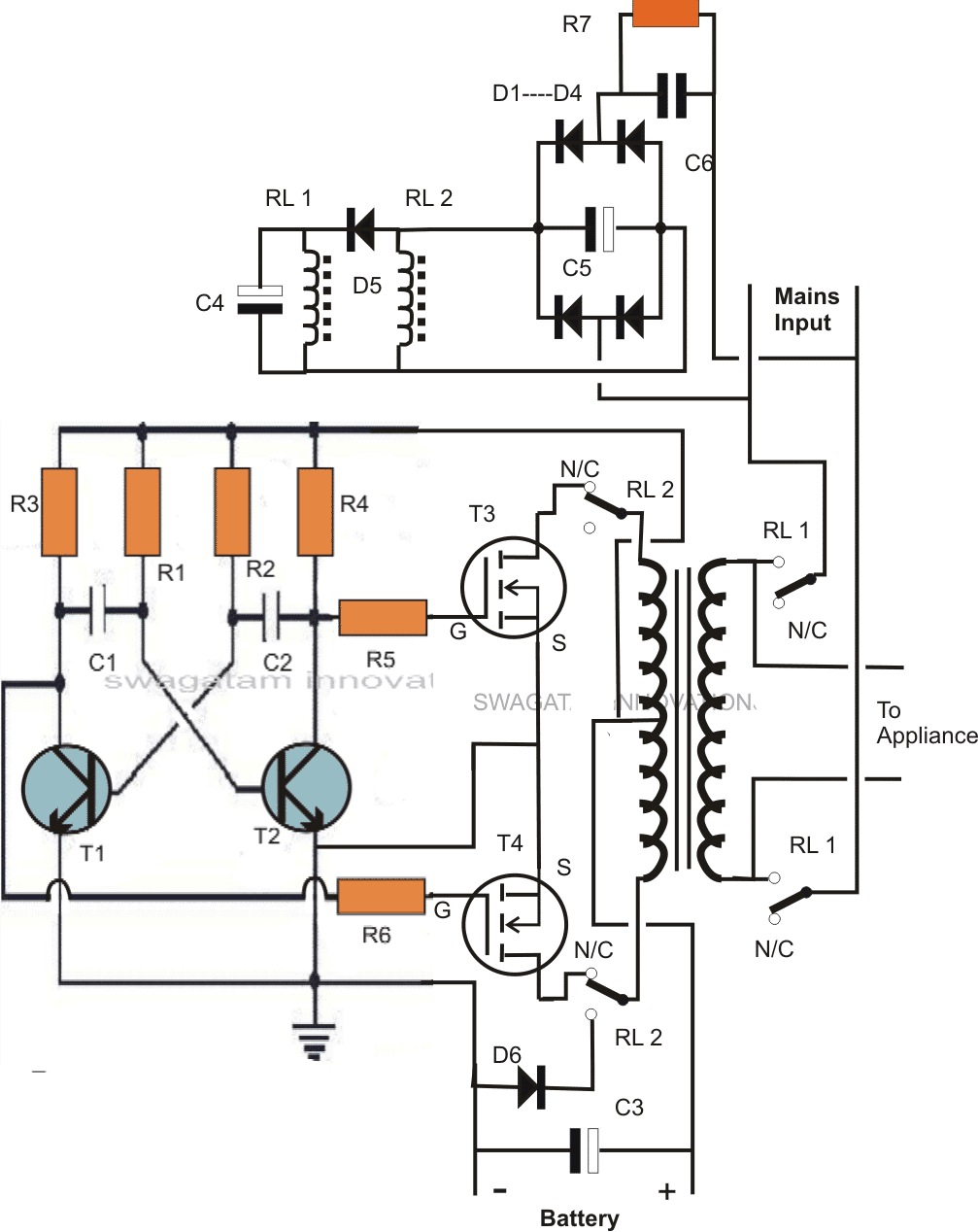
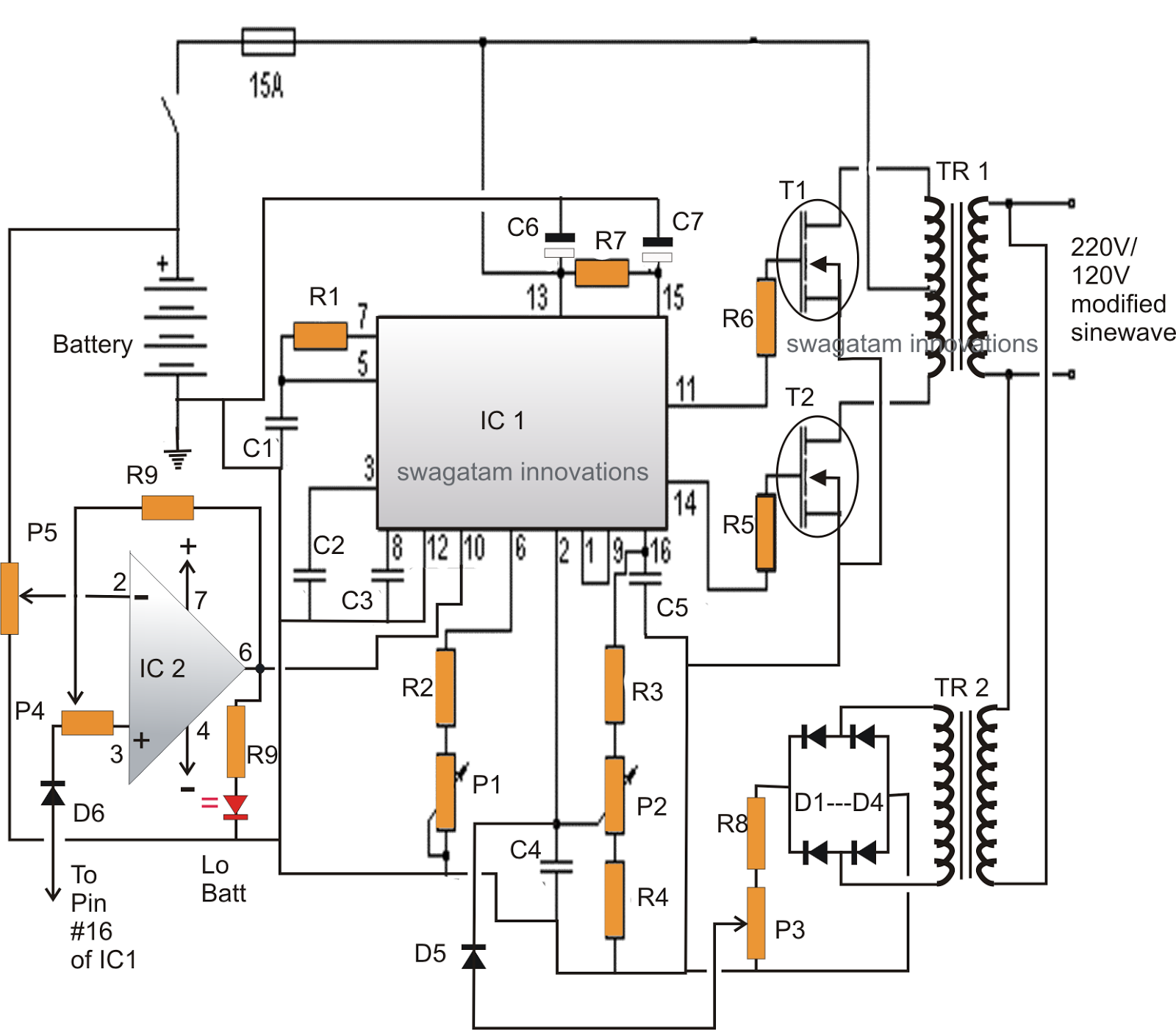
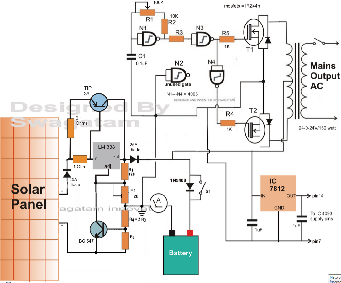
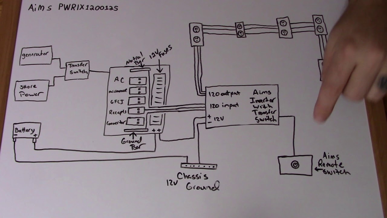


p inverter battery charger circuit many circuits 22 05 2017 inverter battery charger circuit battery charger circuit sg3524 battery charger circuit float charger circuit many circuits this is an electronic circuit sharing and tutorial blog which offers designed and tested circuits for free p p 500 watt inverter circuit with battery charger homemade circuit 30 11 2019 to keep the design simple yet effective i have avoided the use an automatic cut off for the battery charger here and have also ensured a single common transformer is used for the inverter and the charger operations the complete circuit diagram for the proposed 500 watt inverter with battery charger can be seen below rv inverter charger wiring diagram free wiring diagram collection of rv inverter charger wiring diagram a wiring diagram is a simplified conventional photographic representation of an electrical circuit it shows the components of the circuit as simplified shapes and the power as well as signal connections between the devices inverter circuit diagram with charger hasil pencarian gambar here is the circuit diagram of a simple 100 watt inverter using ic cd4047 and mosfet irf540 application report sprabt0 january 2013 1 grid connected micro solar inverter implement using a c2000 mcu jason tao vieri xue mcu dmcdps sae team solar panel inverter circuit diagram circuit diagram images 11 03 2017 share on tumblr inverter circuit gives alternating current ac output from battery power source but the battery requires constant dc supply to get charge so the every inverter circuit contains rectifier and battery charger segment we need to provide ac input power to those circuits then only we can get ac output from inverter circuit when there is no ac supply outlet we couldn t pv solar inverter circuit diagram theorycircuit assortment of marine inverter charger wiring diagram a wiring diagram is a streamlined traditional photographic representation of an electric circuit p p marine inverter charger wiring diagram free wiring diagram this is the circuit diagram of car battery charger which used scr 2n3896 if the circuit built and setup correctly it will safely charge at 10 amps and automatically regulate down to a trickle charge inverter circuit and products 04 01 2020 inverter circuits being the favorites with these devices we would be discussing one such design incorporating mosfets for powering the output stage of the circuit referring to the diagram we see a very basic inverter design involving a square wave oscillator stage a buffer stage and the power output stage 7 simple inverter circuits you can build at home homemade this is the circuit diagram of car battery charger which used scr 2n3896 if the circuit built and setup correctly it will safely charge at 10 amps and automatically regulate down to a trickle charge this charger can t be used as a power supply without having a battery in place the battery must be connected to get power out car battery charger based scr 2n3896 inverter circuit and circuit diagram of automatic battery charger this automatic battery charger circuit is mainly involves two sections power supply section and load comparison section the main supply voltage 230v 50hz is connected to the primary winding of the center tapped transformer to step down the voltage to 15 0 15v automatic 12v portable battery charger circuit using lm317 p p charger inverter charger inverter inverter charger search inverter charger a charger search a charger
p inverter battery charger circuit many circuits 22 05 2017 inverter battery charger circuit battery charger circuit sg3524 battery charger circuit float charger circuit many circuits this is an electronic circuit sharing and tutorial blog which offers designed and tested circuits for free p p 500 watt inverter circuit with battery charger homemade circuit 30 11 2019 to keep the design simple yet effective i have avoided the use an automatic cut off for the battery charger here and have also ensured a single common transformer is used for the inverter and the charger operations the complete circuit diagram for the proposed 500 watt inverter with battery charger can be seen below rv inverter charger wiring diagram free wiring diagram collection of rv inverter charger wiring diagram a wiring diagram is a simplified conventional photographic representation of an electrical circuit it shows the components of the circuit as simplified shapes and the power as well as signal connections between the devices inverter circuit diagram with charger hasil pencarian gambar here is the circuit diagram of a simple 100 watt inverter using ic cd4047 and mosfet irf540 application report sprabt0 january 2013 1 grid connected micro solar inverter implement using a c2000 mcu jason tao vieri xue mcu dmcdps sae team solar panel inverter circuit diagram circuit diagram images 11 03 2017 share on tumblr inverter circuit gives alternating current ac output from battery power source but the battery requires constant dc supply to get charge so the every inverter circuit contains rectifier and battery charger segment we need to provide ac input power to those circuits then only we can get ac output from inverter circuit when there is no ac supply outlet we couldn t pv solar inverter circuit diagram theorycircuit assortment of marine inverter charger wiring diagram a wiring diagram is a streamlined traditional photographic representation of an electric circuit p p marine inverter charger wiring diagram free wiring diagram this is the circuit diagram of car battery charger which used scr 2n3896 if the circuit built and setup correctly it will safely charge at 10 amps and automatically regulate down to a trickle charge inverter circuit and products 04 01 2020 inverter circuits being the favorites with these devices we would be discussing one such design incorporating mosfets for powering the output stage of the circuit referring to the diagram we see a very basic inverter design involving a square wave oscillator stage a buffer stage and the power output stage 7 simple inverter circuits you can build at home homemade this is the circuit diagram of car battery charger which used scr 2n3896 if the circuit built and setup correctly it will safely charge at 10 amps and automatically regulate down to a trickle charge this charger can t be used as a power supply without having a battery in place the battery must be connected to get power out car battery charger based scr 2n3896 inverter circuit and circuit diagram of automatic battery charger this automatic battery charger circuit is mainly involves two sections power supply section and load comparison section the main supply voltage 230v 50hz is connected to the primary winding of the center tapped transformer to step down the voltage to 15 0 15v automatic 12v portable battery charger circuit using lm317 p p charger inverter charger inverter inverter charger search inverter charger a charger search a charger
p inverter battery charger circuit many circuits 22 05 2017 inverter battery charger circuit battery charger circuit sg3524 battery charger circuit float charger circuit many circuits this is an electronic circuit sharing and tutorial blog which offers designed and tested circuits for free p p 500 watt inverter circuit with battery charger homemade circuit 30 11 2019 to keep the design simple yet effective i have avoided the use an automatic cut off for the battery charger here and have also ensured a single common transformer is used for the inverter and the charger operations the complete circuit diagram for the proposed 500 watt inverter with battery charger can be seen below rv inverter charger wiring diagram free wiring diagram collection of rv inverter charger wiring diagram a wiring diagram is a simplified conventional photographic representation of an electrical circuit it shows the components of the circuit as simplified shapes and the power as well as signal connections between the devices inverter circuit diagram with charger hasil pencarian gambar here is the circuit diagram of a simple 100 watt inverter using ic cd4047 and mosfet irf540 application report sprabt0 january 2013 1 grid connected micro solar inverter implement using a c2000 mcu jason tao vieri xue mcu dmcdps sae team solar panel inverter circuit diagram circuit diagram images 11 03 2017 share on tumblr inverter circuit gives alternating current ac output from battery power source but the battery requires constant dc supply to get charge so the every inverter circuit contains rectifier and battery charger segment we need to provide ac input power to those circuits then only we can get ac output from inverter circuit when there is no ac supply outlet we couldn t pv solar inverter circuit diagram theorycircuit assortment of marine inverter charger wiring diagram a wiring diagram is a streamlined traditional photographic representation of an electric circuit p p marine inverter charger wiring diagram free wiring diagram this is the circuit diagram of car battery charger which used scr 2n3896 if the circuit built and setup correctly it will safely charge at 10 amps and automatically regulate down to a trickle charge inverter circuit and products 04 01 2020 inverter circuits being the favorites with these devices we would be discussing one such design incorporating mosfets for powering the output stage of the circuit referring to the diagram we see a very basic inverter design involving a square wave oscillator stage a buffer stage and the power output stage 7 simple inverter circuits you can build at home homemade this is the circuit diagram of car battery charger which used scr 2n3896 if the circuit built and setup correctly it will safely charge at 10 amps and automatically regulate down to a trickle charge this charger can t be used as a power supply without having a battery in place the battery must be connected to get power out car battery charger based scr 2n3896 inverter circuit and circuit diagram of automatic battery charger this automatic battery charger circuit is mainly involves two sections power supply section and load comparison section the main supply voltage 230v 50hz is connected to the primary winding of the center tapped transformer to step down the voltage to 15 0 15v automatic 12v portable battery charger circuit using lm317 p p charger inverter charger inverter inverter charger search inverter charger a charger search a charger
inverter adalah,inverter ac,inverter ac adalah,inverter ac ke dc,inverter aki,inverter ac to dc,inverter abb,inverter artinya,inverter ac ke ac,inverter aki motor,circuit adalah,circuit analysis,circuit and packet switching,circuit app,circuit arcade bar,cricut air 2,circuit apartments,circuit abbreviation,circuit assembly,circuit analysis problems,diagram alir,diagram alir penelitian,diagram adalah,diagram activity,diagram alir adalah,diagram aktivitas,diagram alir proses produksi,diagram analisis swot,diagram arus data,diagram alir data,with all i am,with all i am lyrics,with artinya,with all i am chord,with all due respect,with arms wide open,with a grain of salt,with all due respect meaning,with all my heart,with a little help from my friends lyrics,charger aki,charger aki mobil,charger asus,charger aki motor,charger asus laptop,charger aukey,charger anker,charger apple watch,charger aki otomatis,charger acer


