inverter circuit diagram using mosfet
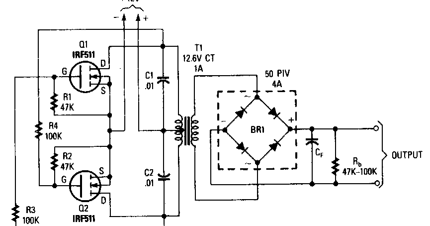

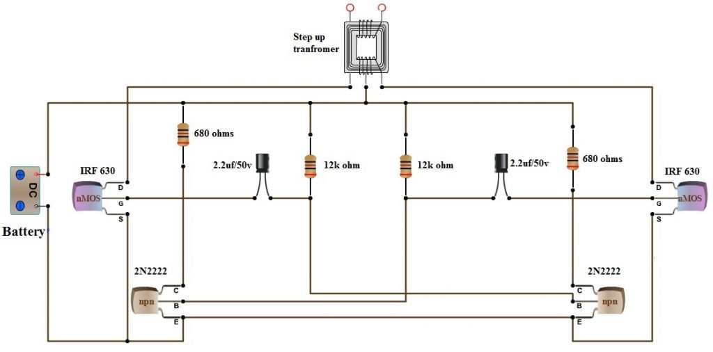
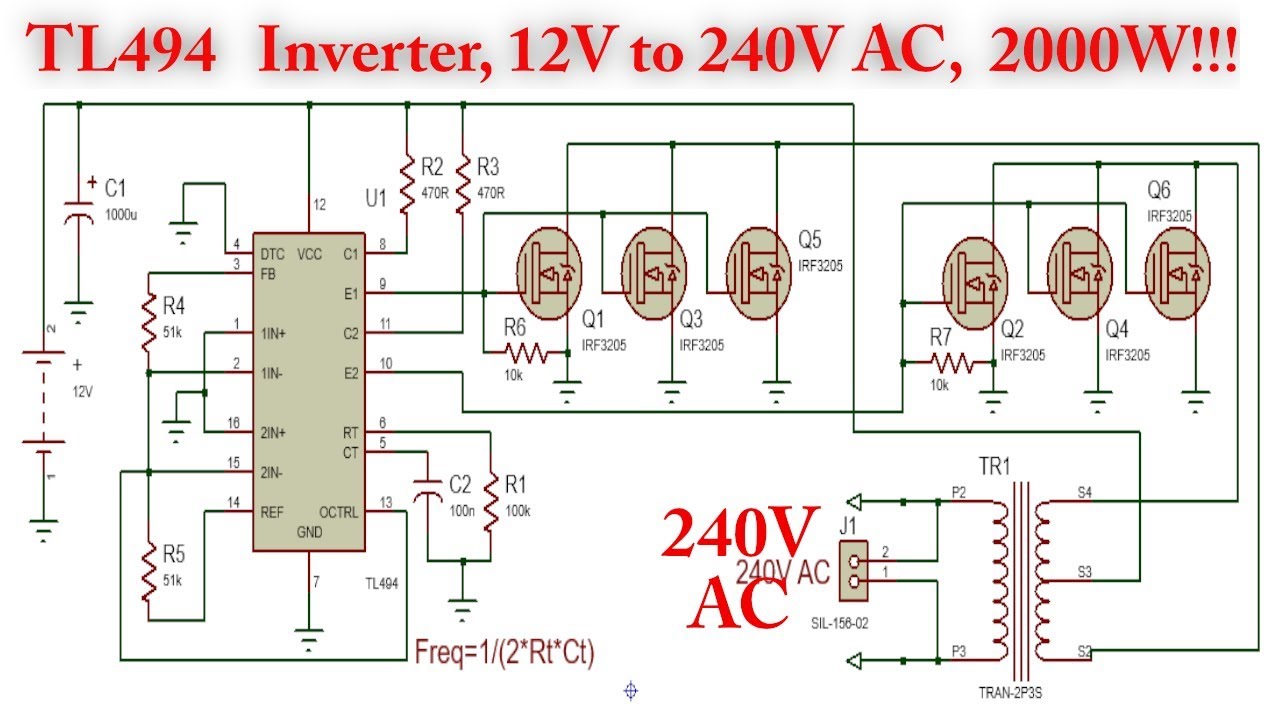


p simple low power inverter circuit 12v dc to 230v or 110v ac 04 07 2012 simple low power inverter circuit 12v dc to 230v or 110v ac diagram using cd4047 and irfz44 power mosfet gallery of electronic circuits and projects providing lot of diy circuit diagrams robotics microcontroller projects electronic development tools p p ic 555 inverter circuit using mosfet 22 09 2019 555 inverter circuit using mosfet in the circuit above is completely circuit diagram of this project i use ic ne555 timer is a square wave frequency generator output of 50hz the frequency is determined with r2 resistor and c1 capacitor then we use both n type mosfet irf540 q2 q3 to drive a transformer coil primary winding 500 watt inverter circuit diagram using mosfet grow amis 500 watt inverter using mosfet battery full charge indicator circuit diagram dosto jaisa ki aap sabhi jante hai ki maine 500 watt inverter circuit board local market se puchase kiya tha isliye aaplogo ko inverter ka circuit diagram dene me mujhe pareshani aa rahi thi lekin ab maine ye inverter circuit diagram bana liya hai to aap sabhi is circuit diagram ka use kar ke khud ka inverter bana inverter circuit diagram using mosfet hasil pencarian gambar in this post we are going to construct a simplest 12vdc to 230vac inverter using transistor and mosfets we will learn different stages in an inverter circuit circuit diagram of the inverter analysis of this inverter s waveform understanding astable multivibrator maximum power output of an inverter advantages and disadvantages of this simple 12v to 230vac inverter circuit mosfet diy electronics 20 03 2019 using 4 n channel mosfets for the inverter the proposed h bridge inverter circuit having 4 n channel mosfets tries to overcome this problem by introducing a higher voltage bootstrapping network for operating the high side mosfets h bridge inverter circuit using 4 n channel mosfets homemade 21 01 2016 to design a 100 watt inverter read simple 100 watt inverter 12v dc to 220v ac converter circuit using astable multivibrator inverter circuits can either use thyristors as switching devices or transistors normally for low and medium power applications power transistors are used p p how to make 12v dc to 220v ac converter inverter circuit design 17 12 2019 mosfet behaves as a better switch than bjt because the offset voltage does not exist in mos switches mosfet inverter circuits inverter circuit is one of the fundamental building blocks in digital circuit design not to be confused with a power inverter mosfet circuits electrical4u this is the scheme diagram of 500w power inverter circuit which build using 10 pieces of well known npn power transistor 2n3055 to amplify the ac signal produced by multivibrator the frequency generator multivibrator is built based on transistors too all of the components is easy to gathered from the electronic store inverter circuit and products 16 04 2017 pwm pulse width modulation signal based inverters are produce output as pure sine wave and it can be used for any electric appliance that meets the inverter output range simple and powerful pwm inverter circuit diagram designed with ic sg3524 regulating pulse width modulator gives upto 230v ac from 12v dc supply pwm inverter circuit diagram pwm inverter circuit ic based simple 12v to 240v inverter using mosfet ic 4047 in this tutorial we will show you how to make simple ic based inverter circuit you can watch the video which is embedded in this step for construction parts list circuit diagram amp testing or you can continue reading the post for further det ic based simple 12v to 240v inverter using mosfet ic 4047 with p p
p simple low power inverter circuit 12v dc to 230v or 110v ac 04 07 2012 simple low power inverter circuit 12v dc to 230v or 110v ac diagram using cd4047 and irfz44 power mosfet gallery of electronic circuits and projects providing lot of diy circuit diagrams robotics microcontroller projects electronic development tools p p ic 555 inverter circuit using mosfet 22 09 2019 555 inverter circuit using mosfet in the circuit above is completely circuit diagram of this project i use ic ne555 timer is a square wave frequency generator output of 50hz the frequency is determined with r2 resistor and c1 capacitor then we use both n type mosfet irf540 q2 q3 to drive a transformer coil primary winding 500 watt inverter circuit diagram using mosfet grow amis 500 watt inverter using mosfet battery full charge indicator circuit diagram dosto jaisa ki aap sabhi jante hai ki maine 500 watt inverter circuit board local market se puchase kiya tha isliye aaplogo ko inverter ka circuit diagram dene me mujhe pareshani aa rahi thi lekin ab maine ye inverter circuit diagram bana liya hai to aap sabhi is circuit diagram ka use kar ke khud ka inverter bana inverter circuit diagram using mosfet hasil pencarian gambar in this post we are going to construct a simplest 12vdc to 230vac inverter using transistor and mosfets we will learn different stages in an inverter circuit circuit diagram of the inverter analysis of this inverter s waveform understanding astable multivibrator maximum power output of an inverter advantages and disadvantages of this simple 12v to 230vac inverter circuit mosfet diy electronics 20 03 2019 using 4 n channel mosfets for the inverter the proposed h bridge inverter circuit having 4 n channel mosfets tries to overcome this problem by introducing a higher voltage bootstrapping network for operating the high side mosfets h bridge inverter circuit using 4 n channel mosfets homemade 21 01 2016 to design a 100 watt inverter read simple 100 watt inverter 12v dc to 220v ac converter circuit using astable multivibrator inverter circuits can either use thyristors as switching devices or transistors normally for low and medium power applications power transistors are used p p how to make 12v dc to 220v ac converter inverter circuit design 17 12 2019 mosfet behaves as a better switch than bjt because the offset voltage does not exist in mos switches mosfet inverter circuits inverter circuit is one of the fundamental building blocks in digital circuit design not to be confused with a power inverter mosfet circuits electrical4u this is the scheme diagram of 500w power inverter circuit which build using 10 pieces of well known npn power transistor 2n3055 to amplify the ac signal produced by multivibrator the frequency generator multivibrator is built based on transistors too all of the components is easy to gathered from the electronic store inverter circuit and products 16 04 2017 pwm pulse width modulation signal based inverters are produce output as pure sine wave and it can be used for any electric appliance that meets the inverter output range simple and powerful pwm inverter circuit diagram designed with ic sg3524 regulating pulse width modulator gives upto 230v ac from 12v dc supply pwm inverter circuit diagram pwm inverter circuit ic based simple 12v to 240v inverter using mosfet ic 4047 in this tutorial we will show you how to make simple ic based inverter circuit you can watch the video which is embedded in this step for construction parts list circuit diagram amp testing or you can continue reading the post for further det ic based simple 12v to 240v inverter using mosfet ic 4047 with p p
p simple low power inverter circuit 12v dc to 230v or 110v ac 04 07 2012 simple low power inverter circuit 12v dc to 230v or 110v ac diagram using cd4047 and irfz44 power mosfet gallery of electronic circuits and projects providing lot of diy circuit diagrams robotics microcontroller projects electronic development tools p p ic 555 inverter circuit using mosfet 22 09 2019 555 inverter circuit using mosfet in the circuit above is completely circuit diagram of this project i use ic ne555 timer is a square wave frequency generator output of 50hz the frequency is determined with r2 resistor and c1 capacitor then we use both n type mosfet irf540 q2 q3 to drive a transformer coil primary winding 500 watt inverter circuit diagram using mosfet grow amis 500 watt inverter using mosfet battery full charge indicator circuit diagram dosto jaisa ki aap sabhi jante hai ki maine 500 watt inverter circuit board local market se puchase kiya tha isliye aaplogo ko inverter ka circuit diagram dene me mujhe pareshani aa rahi thi lekin ab maine ye inverter circuit diagram bana liya hai to aap sabhi is circuit diagram ka use kar ke khud ka inverter bana inverter circuit diagram using mosfet hasil pencarian gambar in this post we are going to construct a simplest 12vdc to 230vac inverter using transistor and mosfets we will learn different stages in an inverter circuit circuit diagram of the inverter analysis of this inverter s waveform understanding astable multivibrator maximum power output of an inverter advantages and disadvantages of this simple 12v to 230vac inverter circuit mosfet diy electronics 20 03 2019 using 4 n channel mosfets for the inverter the proposed h bridge inverter circuit having 4 n channel mosfets tries to overcome this problem by introducing a higher voltage bootstrapping network for operating the high side mosfets h bridge inverter circuit using 4 n channel mosfets homemade 21 01 2016 to design a 100 watt inverter read simple 100 watt inverter 12v dc to 220v ac converter circuit using astable multivibrator inverter circuits can either use thyristors as switching devices or transistors normally for low and medium power applications power transistors are used p p how to make 12v dc to 220v ac converter inverter circuit design 17 12 2019 mosfet behaves as a better switch than bjt because the offset voltage does not exist in mos switches mosfet inverter circuits inverter circuit is one of the fundamental building blocks in digital circuit design not to be confused with a power inverter mosfet circuits electrical4u this is the scheme diagram of 500w power inverter circuit which build using 10 pieces of well known npn power transistor 2n3055 to amplify the ac signal produced by multivibrator the frequency generator multivibrator is built based on transistors too all of the components is easy to gathered from the electronic store inverter circuit and products 16 04 2017 pwm pulse width modulation signal based inverters are produce output as pure sine wave and it can be used for any electric appliance that meets the inverter output range simple and powerful pwm inverter circuit diagram designed with ic sg3524 regulating pulse width modulator gives upto 230v ac from 12v dc supply pwm inverter circuit diagram pwm inverter circuit ic based simple 12v to 240v inverter using mosfet ic 4047 in this tutorial we will show you how to make simple ic based inverter circuit you can watch the video which is embedded in this step for construction parts list circuit diagram amp testing or you can continue reading the post for further det ic based simple 12v to 240v inverter using mosfet ic 4047 with p p
inverter adalah,inverter ac,inverter ac adalah,inverter ac ke dc,inverter aki,inverter ac to dc,inverter abb,inverter artinya,inverter ac ke ac,inverter aki motor,circuit adalah,circuit analysis,circuit and packet switching,circuit app,circuit arcade bar,cricut air 2,circuit apartments,circuit abbreviation,circuit assembly,circuit analysis problems,diagram alir,diagram alir penelitian,diagram adalah,diagram activity,diagram alir adalah,diagram aktivitas,diagram alir proses produksi,diagram analisis swot,diagram arus data,diagram alir data,using atm in bali,using artinya,using adalah,using at in on,using as in a sentence,using apostrophes,using airpods on plane,using aircrack-ng,using and in excel,using airpods with android,mosfet adalah,mosfet amplifier,mosfet as a switch,mosfet automation,mosfet aeg,mosfet arduino,mosfet applications,mosfet amplifier circuit for subwoofer,mosfet ampere besar,mosfet airsoft


