inverter circuit diagram using microcontroller
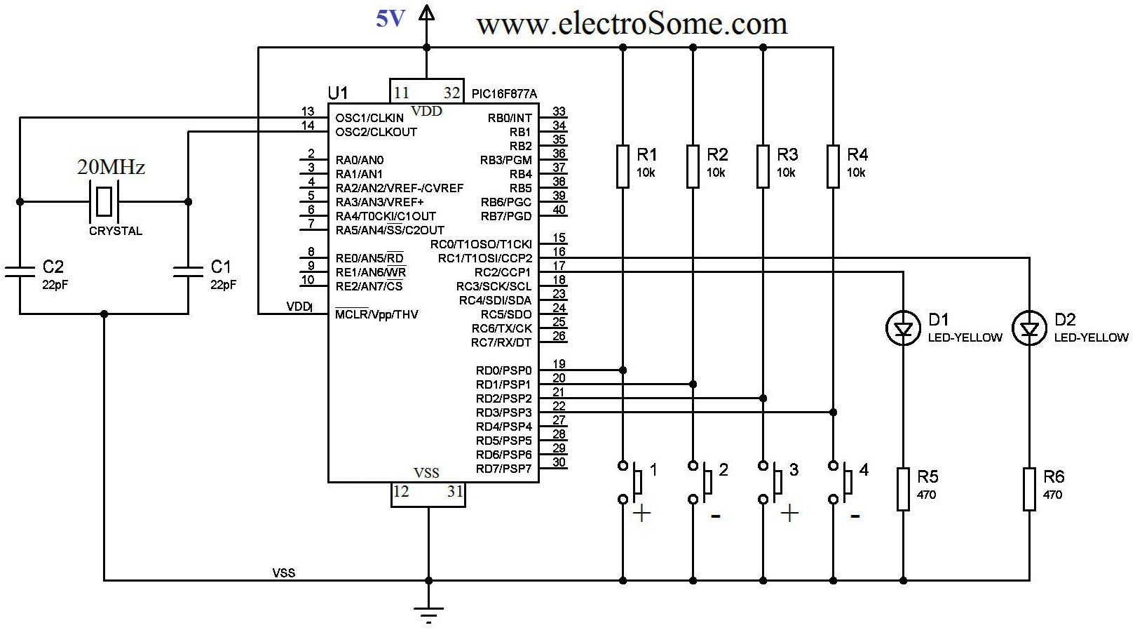
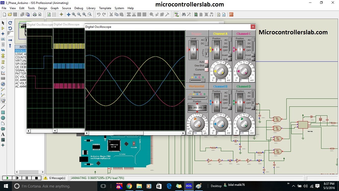


p pure sine wave inverter circuit diagram microcontrollers lab sine wave inverter circuit diagram with complete step by step program and coding in this article i will discuss how to use push pull converter sinusoidal pulse width modulation h bridge and low pass lc filter to make pure sine wave inverter circuit diagram p p modified sine wave inverter using pic microcontroller modified sine wave inverter is designed to using pic microcontroller and push pull topology mosfet used as a switches in push pull operated through control circuit in such a way that iron core transformer produced step up battery voltage having modified sine wave form sine wave inverter circuit using pic16f72 making easy circuits 31 03 2018 the post details comprehensively regarding how to build a pure sinewave inverter circuit using microcontroller circuit with pic16f72 the following image shows the complete circuit diagram of the sinewave inverter the images are divided into two in order to fit inside the page please join them together after printing the two images inverter circuit diagram using microcontroller hasil pencarian gambar three level pwm dc ac inverter using a microcontroller oliver rich william chapman mqp terms a b c 2011 2012 advisor professor stephen j bitar three level pwm dc ac inverter using a microcontroller 16f877a microcontroller units mcus that can achieve high level inverter control and therefor this microcontroller is the heart of the system and controls entire system the microcontroller is programmed using embedded c compiler and in specific mikroc pro to generate sine pulse width modulated spwm pulses which are used to drive h bridge by microcontroller based power inverter 04 07 2012 simple low power inverter circuit 12v dc to 230v or 110v ac diagram using cd4047 and irfz44 power mosfet gallery of electronic circuits and projects providing lot of diy circuit diagrams robotics microcontroller projects electronic development tools p p simple low power inverter circuit 12v dc to 230v or 110v ac 19 04 2016 complete circuit diagram and code of pure sine wave inverter using pic microcontroller and spwm generation using pic16f877a microcontroller contact me at bilalmalikuet gmail com to purchase code pure sine wave inverter using pic microcontroller youtube 05 11 2012 pure sine wave inverter consist of a microcontroller unit which generates a switching signal of 15 khz an h bridge circuit to convert the signal into ac a low pass lc filter circuit to block the high frequency components and the transformer unit to step up the voltages block diagram of sine wave circuit is given below pure sine wave inverter design with code the engineering 04 09 2012 simple pwm inverter circuit diagram using pwm chip sg3524 gallery of electronic circuits and projects providing lot of diy circuit diagrams robotics microcontroller projects electronic development tools simple pwm inverter circuit diagram using pwm chip sg3524 24 09 2017 circuit diagram construction working this inverter circuit have three stages and a 12v 5 0ah sla battery as a dc bias to show this circuit simple and neat i have removed battery charger circuit the first stage of this circuit is arduino micro controller board and it is programmed to give arduino inverter circuit find every electronics circuit diagram p p
p pure sine wave inverter circuit diagram microcontrollers lab sine wave inverter circuit diagram with complete step by step program and coding in this article i will discuss how to use push pull converter sinusoidal pulse width modulation h bridge and low pass lc filter to make pure sine wave inverter circuit diagram p p modified sine wave inverter using pic microcontroller modified sine wave inverter is designed to using pic microcontroller and push pull topology mosfet used as a switches in push pull operated through control circuit in such a way that iron core transformer produced step up battery voltage having modified sine wave form sine wave inverter circuit using pic16f72 making easy circuits 31 03 2018 the post details comprehensively regarding how to build a pure sinewave inverter circuit using microcontroller circuit with pic16f72 the following image shows the complete circuit diagram of the sinewave inverter the images are divided into two in order to fit inside the page please join them together after printing the two images inverter circuit diagram using microcontroller hasil pencarian gambar three level pwm dc ac inverter using a microcontroller oliver rich william chapman mqp terms a b c 2011 2012 advisor professor stephen j bitar three level pwm dc ac inverter using a microcontroller 16f877a microcontroller units mcus that can achieve high level inverter control and therefor this microcontroller is the heart of the system and controls entire system the microcontroller is programmed using embedded c compiler and in specific mikroc pro to generate sine pulse width modulated spwm pulses which are used to drive h bridge by microcontroller based power inverter 04 07 2012 simple low power inverter circuit 12v dc to 230v or 110v ac diagram using cd4047 and irfz44 power mosfet gallery of electronic circuits and projects providing lot of diy circuit diagrams robotics microcontroller projects electronic development tools p p simple low power inverter circuit 12v dc to 230v or 110v ac 19 04 2016 complete circuit diagram and code of pure sine wave inverter using pic microcontroller and spwm generation using pic16f877a microcontroller contact me at bilalmalikuet gmail com to purchase code pure sine wave inverter using pic microcontroller youtube 05 11 2012 pure sine wave inverter consist of a microcontroller unit which generates a switching signal of 15 khz an h bridge circuit to convert the signal into ac a low pass lc filter circuit to block the high frequency components and the transformer unit to step up the voltages block diagram of sine wave circuit is given below pure sine wave inverter design with code the engineering 04 09 2012 simple pwm inverter circuit diagram using pwm chip sg3524 gallery of electronic circuits and projects providing lot of diy circuit diagrams robotics microcontroller projects electronic development tools simple pwm inverter circuit diagram using pwm chip sg3524 24 09 2017 circuit diagram construction working this inverter circuit have three stages and a 12v 5 0ah sla battery as a dc bias to show this circuit simple and neat i have removed battery charger circuit the first stage of this circuit is arduino micro controller board and it is programmed to give arduino inverter circuit find every electronics circuit diagram p p
p pure sine wave inverter circuit diagram microcontrollers lab sine wave inverter circuit diagram with complete step by step program and coding in this article i will discuss how to use push pull converter sinusoidal pulse width modulation h bridge and low pass lc filter to make pure sine wave inverter circuit diagram p p modified sine wave inverter using pic microcontroller modified sine wave inverter is designed to using pic microcontroller and push pull topology mosfet used as a switches in push pull operated through control circuit in such a way that iron core transformer produced step up battery voltage having modified sine wave form sine wave inverter circuit using pic16f72 making easy circuits 31 03 2018 the post details comprehensively regarding how to build a pure sinewave inverter circuit using microcontroller circuit with pic16f72 the following image shows the complete circuit diagram of the sinewave inverter the images are divided into two in order to fit inside the page please join them together after printing the two images inverter circuit diagram using microcontroller hasil pencarian gambar three level pwm dc ac inverter using a microcontroller oliver rich william chapman mqp terms a b c 2011 2012 advisor professor stephen j bitar three level pwm dc ac inverter using a microcontroller 16f877a microcontroller units mcus that can achieve high level inverter control and therefor this microcontroller is the heart of the system and controls entire system the microcontroller is programmed using embedded c compiler and in specific mikroc pro to generate sine pulse width modulated spwm pulses which are used to drive h bridge by microcontroller based power inverter 04 07 2012 simple low power inverter circuit 12v dc to 230v or 110v ac diagram using cd4047 and irfz44 power mosfet gallery of electronic circuits and projects providing lot of diy circuit diagrams robotics microcontroller projects electronic development tools p p simple low power inverter circuit 12v dc to 230v or 110v ac 19 04 2016 complete circuit diagram and code of pure sine wave inverter using pic microcontroller and spwm generation using pic16f877a microcontroller contact me at bilalmalikuet gmail com to purchase code pure sine wave inverter using pic microcontroller youtube 05 11 2012 pure sine wave inverter consist of a microcontroller unit which generates a switching signal of 15 khz an h bridge circuit to convert the signal into ac a low pass lc filter circuit to block the high frequency components and the transformer unit to step up the voltages block diagram of sine wave circuit is given below pure sine wave inverter design with code the engineering 04 09 2012 simple pwm inverter circuit diagram using pwm chip sg3524 gallery of electronic circuits and projects providing lot of diy circuit diagrams robotics microcontroller projects electronic development tools simple pwm inverter circuit diagram using pwm chip sg3524 24 09 2017 circuit diagram construction working this inverter circuit have three stages and a 12v 5 0ah sla battery as a dc bias to show this circuit simple and neat i have removed battery charger circuit the first stage of this circuit is arduino micro controller board and it is programmed to give arduino inverter circuit find every electronics circuit diagram p p
inverter adalah,inverter ac,inverter ac adalah,inverter ac ke dc,inverter aki,inverter ac to dc,inverter abb,inverter artinya,inverter ac ke ac,inverter aki motor,circuit adalah,circuit analysis,circuit and packet switching,circuit app,circuit arcade bar,cricut air 2,circuit apartments,circuit abbreviation,circuit assembly,circuit analysis problems,diagram alir,diagram alir penelitian,diagram adalah,diagram activity,diagram alir adalah,diagram aktivitas,diagram alir proses produksi,diagram analisis swot,diagram arus data,diagram alir data,using atm in bali,using artinya,using adalah,using at in on,using as in a sentence,using apostrophes,using airpods on plane,using aircrack-ng,using and in excel,using airpods with android,microcontroller adalah,microcontroller arduino,microcontroller arduino uno,microcontroller arduino adalah,microcontroller applications,microcontroller architecture,microcontroller and microprocessor,microcontroller atmega328,microcontroller at89s52,microcontroller and embedded system


