100w inverter circuit diagram with pcb layout


p 100w transistored inverter circuit diagram with pcb layout the following diagram is an inverter circuit which will give you 220v ac 50hz with maximum power output of 100w this inverter built using transistors for both the square wave generator module and the amplifier module inverter diagram the q1 and q2 used generate square wave p p cd4047be 100w inverter circuit diagram with pcb layout 18 07 2019 cd4047be 100w inverter circuit diagram with pcb layout the inverter circuit is working based on the oscillating ic of cd4047 it is a general purpose inverter ic you will get in all the electronic shops 100 watt power inverter circuit diagram and pcb inverter 04 07 2019 make 100 watt power inverter at home easily you will get the free circuit and pcb layout here its a 12 volt battery inverter and it will convert 12v dc to 12v ac supply with 100w output power 100w inverter circuit diagram with pcb layout hasil pencarian gambar inverter diagram the q1 and q2 used generate square wave q5 q8 amplify the signal and the transformer to increase the ac square wave current from 12vac to 220v ac 50hz inverter pcb layout the following image is the bottom copper pcb layout and to layout for the components placement you may use universal pcb veroboard to make it easier 100w transistored inverter circuit diagram with pcb layout the following diagram is an inverter circuit which will give you 220v ac 50hz with maximum power output of 100w this inverter built using transistors for both the square wave generator module and the amplifier module inverter diagram the q1 and q2 used generate square wave q5 q8 amplify the 100w transistored inverter circuit diagram with pcb layout 27 11 2018 100 watt inverter circuit diagram parts list design tips inverters are devices that convert dc input supply to ac alternating current they are also called power inverters power inverters have numerous applications in power electronics field p p 100 watt inverter circuit diagram parts list design tips 1000w power inverter circuit diagram this is the power inverter circuit based mosfet rfp50n06 the inverter capable to handle loads up to 1000w it s depended on your power inverter transformer the rfp50n06 fets are rated at 50 amps and 60 volts heatsink is required for cooling the mosfets 1000w power inverter electronic circuit diagram inverter pcb layout design 12v car battery is recomended to be used as the input transistor 2n3055 is used as the amplifier it will deliver the power output up to 100w and you can use this inverter for battery charger emergency light and other electronic appliances inverter pcb layout design inverter circuit and products 29 07 2018 100watt inverter circuit inverter circuits are among the easiest circuits to build for newbies here is the circuit diagram of a simple 100 watt inverter using ic cd4047 and mosfet irf540 the circuit is simple low cost and can be even assembled on a veroboard circuit diagram components battery 12v 7ah ic cd4047 1 nos mosfet simple 100w inverter circuit working and circuit diagram 22 08 2015 simple 100w inverter circuit diagram explanation in the circuit diagram we can observe that 12v battery is connecter to the diode led and also connected to the pin8 of the ic 4047 which is vcc or power supply pin and also to pin 4 and 5 which are astable and complement astable of the ic simple 100w inverter circuit diagram and its working p p
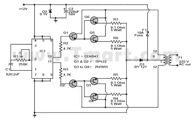
p 100w transistored inverter circuit diagram with pcb layout the following diagram is an inverter circuit which will give you 220v ac 50hz with maximum power output of 100w this inverter built using transistors for both the square wave generator module and the amplifier module inverter diagram the q1 and q2 used generate square wave p p cd4047be 100w inverter circuit diagram with pcb layout 18 07 2019 cd4047be 100w inverter circuit diagram with pcb layout the inverter circuit is working based on the oscillating ic of cd4047 it is a general purpose inverter ic you will get in all the electronic shops 100 watt power inverter circuit diagram and pcb inverter 04 07 2019 make 100 watt power inverter at home easily you will get the free circuit and pcb layout here its a 12 volt battery inverter and it will convert 12v dc to 12v ac supply with 100w output power 100w inverter circuit diagram with pcb layout hasil pencarian gambar inverter diagram the q1 and q2 used generate square wave q5 q8 amplify the signal and the transformer to increase the ac square wave current from 12vac to 220v ac 50hz inverter pcb layout the following image is the bottom copper pcb layout and to layout for the components placement you may use universal pcb veroboard to make it easier 100w transistored inverter circuit diagram with pcb layout the following diagram is an inverter circuit which will give you 220v ac 50hz with maximum power output of 100w this inverter built using transistors for both the square wave generator module and the amplifier module inverter diagram the q1 and q2 used generate square wave q5 q8 amplify the 100w transistored inverter circuit diagram with pcb layout 27 11 2018 100 watt inverter circuit diagram parts list design tips inverters are devices that convert dc input supply to ac alternating current they are also called power inverters power inverters have numerous applications in power electronics field p p 100 watt inverter circuit diagram parts list design tips 1000w power inverter circuit diagram this is the power inverter circuit based mosfet rfp50n06 the inverter capable to handle loads up to 1000w it s depended on your power inverter transformer the rfp50n06 fets are rated at 50 amps and 60 volts heatsink is required for cooling the mosfets 1000w power inverter electronic circuit diagram inverter pcb layout design 12v car battery is recomended to be used as the input transistor 2n3055 is used as the amplifier it will deliver the power output up to 100w and you can use this inverter for battery charger emergency light and other electronic appliances inverter pcb layout design inverter circuit and products 29 07 2018 100watt inverter circuit inverter circuits are among the easiest circuits to build for newbies here is the circuit diagram of a simple 100 watt inverter using ic cd4047 and mosfet irf540 the circuit is simple low cost and can be even assembled on a veroboard circuit diagram components battery 12v 7ah ic cd4047 1 nos mosfet simple 100w inverter circuit working and circuit diagram 22 08 2015 simple 100w inverter circuit diagram explanation in the circuit diagram we can observe that 12v battery is connecter to the diode led and also connected to the pin8 of the ic 4047 which is vcc or power supply pin and also to pin 4 and 5 which are astable and complement astable of the ic simple 100w inverter circuit diagram and its working p p
p 100w transistored inverter circuit diagram with pcb layout the following diagram is an inverter circuit which will give you 220v ac 50hz with maximum power output of 100w this inverter built using transistors for both the square wave generator module and the amplifier module inverter diagram the q1 and q2 used generate square wave p p cd4047be 100w inverter circuit diagram with pcb layout 18 07 2019 cd4047be 100w inverter circuit diagram with pcb layout the inverter circuit is working based on the oscillating ic of cd4047 it is a general purpose inverter ic you will get in all the electronic shops 100 watt power inverter circuit diagram and pcb inverter 04 07 2019 make 100 watt power inverter at home easily you will get the free circuit and pcb layout here its a 12 volt battery inverter and it will convert 12v dc to 12v ac supply with 100w output power 100w inverter circuit diagram with pcb layout hasil pencarian gambar inverter diagram the q1 and q2 used generate square wave q5 q8 amplify the signal and the transformer to increase the ac square wave current from 12vac to 220v ac 50hz inverter pcb layout the following image is the bottom copper pcb layout and to layout for the components placement you may use universal pcb veroboard to make it easier 100w transistored inverter circuit diagram with pcb layout the following diagram is an inverter circuit which will give you 220v ac 50hz with maximum power output of 100w this inverter built using transistors for both the square wave generator module and the amplifier module inverter diagram the q1 and q2 used generate square wave q5 q8 amplify the 100w transistored inverter circuit diagram with pcb layout 27 11 2018 100 watt inverter circuit diagram parts list design tips inverters are devices that convert dc input supply to ac alternating current they are also called power inverters power inverters have numerous applications in power electronics field p p 100 watt inverter circuit diagram parts list design tips 1000w power inverter circuit diagram this is the power inverter circuit based mosfet rfp50n06 the inverter capable to handle loads up to 1000w it s depended on your power inverter transformer the rfp50n06 fets are rated at 50 amps and 60 volts heatsink is required for cooling the mosfets 1000w power inverter electronic circuit diagram inverter pcb layout design 12v car battery is recomended to be used as the input transistor 2n3055 is used as the amplifier it will deliver the power output up to 100w and you can use this inverter for battery charger emergency light and other electronic appliances inverter pcb layout design inverter circuit and products 29 07 2018 100watt inverter circuit inverter circuits are among the easiest circuits to build for newbies here is the circuit diagram of a simple 100 watt inverter using ic cd4047 and mosfet irf540 the circuit is simple low cost and can be even assembled on a veroboard circuit diagram components battery 12v 7ah ic cd4047 1 nos mosfet simple 100w inverter circuit working and circuit diagram 22 08 2015 simple 100w inverter circuit diagram explanation in the circuit diagram we can observe that 12v battery is connecter to the diode led and also connected to the pin8 of the ic 4047 which is vcc or power supply pin and also to pin 4 and 5 which are astable and complement astable of the ic simple 100w inverter circuit diagram and its working p p
100w amplifier,100w aquarium heater,100w amp,100w amplifier circuit,100w amplifier board,100w amplifier price in bangladesh,100w a19 bulb,100w audio amplifier,100w amplifier price,100w amplifier price in sri lanka,inverter adalah,inverter ac,inverter ac adalah,inverter ac ke dc,inverter aki,inverter ac to dc,inverter abb,inverter artinya,inverter ac ke ac,inverter aki motor,circuit adalah,circuit analysis,circuit and packet switching,circuit app,circuit arcade bar,cricut air 2,circuit apartments,circuit abbreviation,circuit assembly,circuit analysis problems,diagram alir,diagram alir penelitian,diagram adalah,diagram activity,diagram alir adalah,diagram aktivitas,diagram alir proses produksi,diagram analisis swot,diagram arus data,diagram alir data,with all i am,with all i am lyrics,with artinya,with all i am chord,with all due respect,with arms wide open,with a grain of salt,with all due respect meaning,with all my heart,with a little help from my friends lyrics,pcb adalah,pcb ac,pcb ac daikin,pcb ac lg,pcb amplifier,pcb assembly,pcb ac sharp,pcb artinya,pcb ac panasonic,pcb ac samsung,layout adalah,layout android,layout apk,layout autocad,layout artinya,layout apartemen,layout apotek,layout app,layout amplop,layout acara


