inverter circuit diagram with overload protection


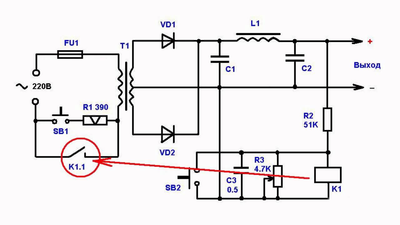

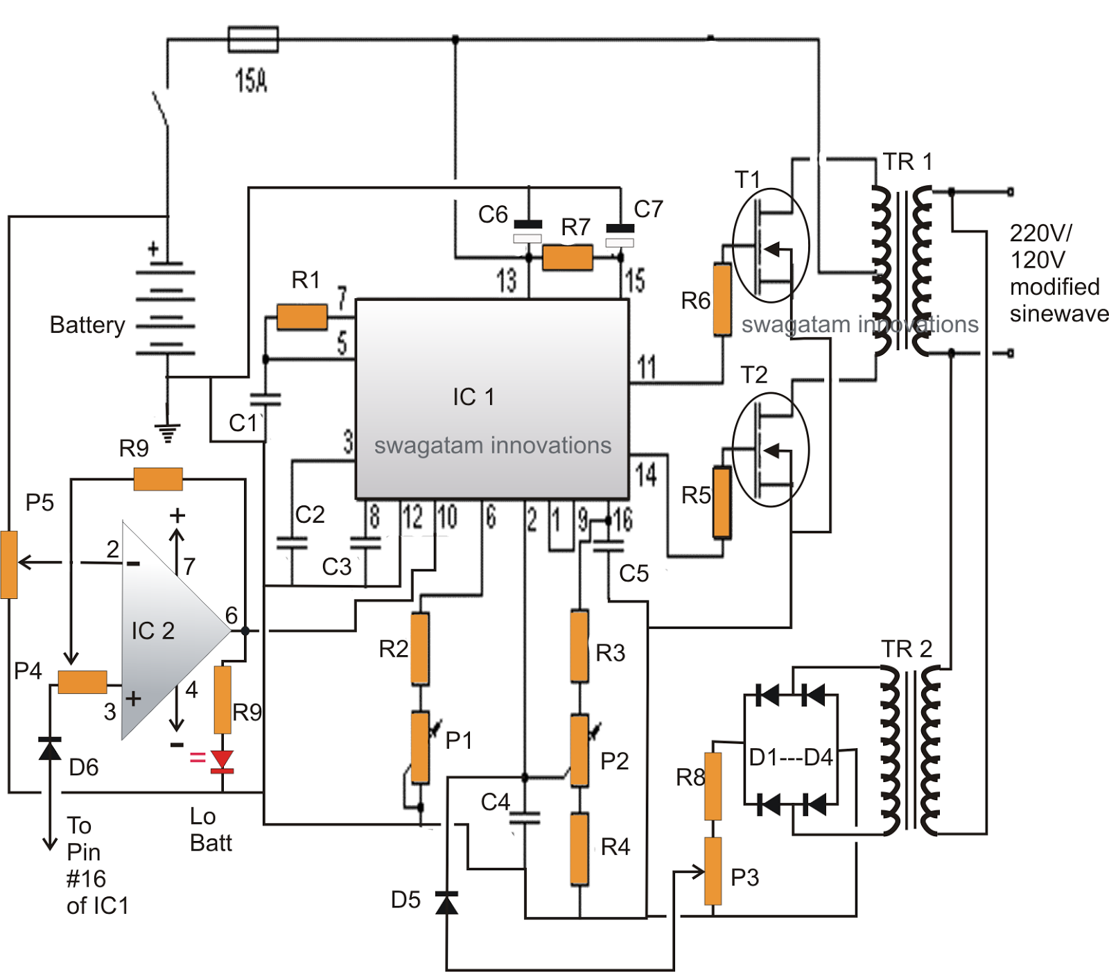
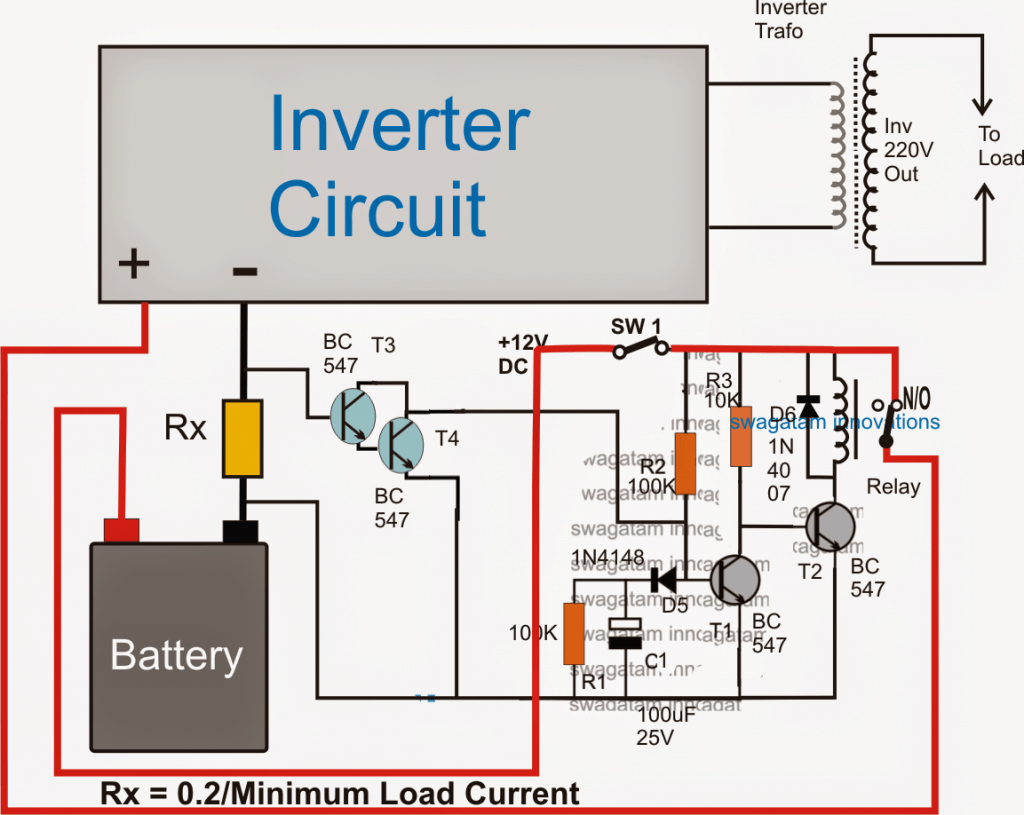

p low battery and overload protection circuit for inverters 13 06 2019 the load terminals in the above diagram is supposed to be connected with the inverter supply terminals this implies that the battery current from the right side has to pass through r1 before reaching the inverter enabling the sensing circuit around r1 to sense a possible over current or overload situation p p inverter protection overload short circuit youtube 29 05 2019 the inverter is easily broken if it is short circuited or overloaded for a long time this simple circuit will protect your inverter if the inverter is shor inverter overload protector electronic circuits diagram an overload condition in an inverter may permanently damage the power transistor array or burn off the transformer some of the domestic inverters sold in the market do not feature an overload shutdown facility while those incorporating this feature come with a price tag the circuit presented here is an overload detector which shuts down the inverter circuit diagram with overload protection hasil pencarian gambar 14 07 2019 the inverter protection circuit lm324 the low voltage and overload issue controlling free pcb layout suitable for using ic sg3525 sg3524 etc it is a very important and useful circuit board for inverter voltage detection and shutdown to protect electrical equipment inverter protection circuit lm324 low voltage and overload i have seen that in sg3525 based power inverter the overload protection module incorporates two opamps why is this so i mean we simple monitor the current and compare it with a reference using one opamp and connect the output of opamp to the pin 10 of sg3525 but many schematics contains 2 opamps in cascade why overload protection circuit in inverter i have made an inverter using tl494 and sg3524 chips but there is no overload protection circuit what changes should i make for the protection circuit p p overload protection circuit in tl494 and sg3524 inverter 29 03 2018 today we see the protection circuit which is divided into three parts are 1 the overload output current protection circuit 2 the output overheat temperature protection circuit 3 the battery checker i m been talking about the the 200 watts home power inverter projects many articles include the following article 1 simple working principle of 200 watts home power inverter project using sg3526n elec 24 05 2017 how to connect the low battery protection circuit and an overload protection circuit to any circuit that uses pulse width modulation ic such as sg3525 sg3524 uc3842 43 44 tl494 etc its good to know and understand the functions of the pins of the pwm ic that you are going to add this function to overload protection circuit and low battery alarm many circuits this is a kind of excellent performance power inverter for home circuit diagram materials are easy to get and the output power can reach 150w this circuit is envisaged frequency in 300hz the purpose is to reduce the inverter transformer size and weight output is square wave power inverter design circuit diagrams 22 04 2019 fet overload current protection this is the overload current protection circuit for a normal power supply it uses a fet to drives a load if you worry that the power supply will damage when the load uses too much current or a output is a short circuit this may help you how it works as the circuit diagram below usually the load work simple overload protection circuits eleccircuit com p p inverter protection search inverter protection
p low battery and overload protection circuit for inverters 13 06 2019 the load terminals in the above diagram is supposed to be connected with the inverter supply terminals this implies that the battery current from the right side has to pass through r1 before reaching the inverter enabling the sensing circuit around r1 to sense a possible over current or overload situation p p inverter protection overload short circuit youtube 29 05 2019 the inverter is easily broken if it is short circuited or overloaded for a long time this simple circuit will protect your inverter if the inverter is shor inverter overload protector electronic circuits diagram an overload condition in an inverter may permanently damage the power transistor array or burn off the transformer some of the domestic inverters sold in the market do not feature an overload shutdown facility while those incorporating this feature come with a price tag the circuit presented here is an overload detector which shuts down the inverter circuit diagram with overload protection hasil pencarian gambar 14 07 2019 the inverter protection circuit lm324 the low voltage and overload issue controlling free pcb layout suitable for using ic sg3525 sg3524 etc it is a very important and useful circuit board for inverter voltage detection and shutdown to protect electrical equipment inverter protection circuit lm324 low voltage and overload i have seen that in sg3525 based power inverter the overload protection module incorporates two opamps why is this so i mean we simple monitor the current and compare it with a reference using one opamp and connect the output of opamp to the pin 10 of sg3525 but many schematics contains 2 opamps in cascade why overload protection circuit in inverter i have made an inverter using tl494 and sg3524 chips but there is no overload protection circuit what changes should i make for the protection circuit p p overload protection circuit in tl494 and sg3524 inverter 29 03 2018 today we see the protection circuit which is divided into three parts are 1 the overload output current protection circuit 2 the output overheat temperature protection circuit 3 the battery checker i m been talking about the the 200 watts home power inverter projects many articles include the following article 1 simple working principle of 200 watts home power inverter project using sg3526n elec 24 05 2017 how to connect the low battery protection circuit and an overload protection circuit to any circuit that uses pulse width modulation ic such as sg3525 sg3524 uc3842 43 44 tl494 etc its good to know and understand the functions of the pins of the pwm ic that you are going to add this function to overload protection circuit and low battery alarm many circuits this is a kind of excellent performance power inverter for home circuit diagram materials are easy to get and the output power can reach 150w this circuit is envisaged frequency in 300hz the purpose is to reduce the inverter transformer size and weight output is square wave power inverter design circuit diagrams 22 04 2019 fet overload current protection this is the overload current protection circuit for a normal power supply it uses a fet to drives a load if you worry that the power supply will damage when the load uses too much current or a output is a short circuit this may help you how it works as the circuit diagram below usually the load work simple overload protection circuits eleccircuit com p p inverter protection search inverter protection
p low battery and overload protection circuit for inverters 13 06 2019 the load terminals in the above diagram is supposed to be connected with the inverter supply terminals this implies that the battery current from the right side has to pass through r1 before reaching the inverter enabling the sensing circuit around r1 to sense a possible over current or overload situation p p inverter protection overload short circuit youtube 29 05 2019 the inverter is easily broken if it is short circuited or overloaded for a long time this simple circuit will protect your inverter if the inverter is shor inverter overload protector electronic circuits diagram an overload condition in an inverter may permanently damage the power transistor array or burn off the transformer some of the domestic inverters sold in the market do not feature an overload shutdown facility while those incorporating this feature come with a price tag the circuit presented here is an overload detector which shuts down the inverter circuit diagram with overload protection hasil pencarian gambar 14 07 2019 the inverter protection circuit lm324 the low voltage and overload issue controlling free pcb layout suitable for using ic sg3525 sg3524 etc it is a very important and useful circuit board for inverter voltage detection and shutdown to protect electrical equipment inverter protection circuit lm324 low voltage and overload i have seen that in sg3525 based power inverter the overload protection module incorporates two opamps why is this so i mean we simple monitor the current and compare it with a reference using one opamp and connect the output of opamp to the pin 10 of sg3525 but many schematics contains 2 opamps in cascade why overload protection circuit in inverter i have made an inverter using tl494 and sg3524 chips but there is no overload protection circuit what changes should i make for the protection circuit p p overload protection circuit in tl494 and sg3524 inverter 29 03 2018 today we see the protection circuit which is divided into three parts are 1 the overload output current protection circuit 2 the output overheat temperature protection circuit 3 the battery checker i m been talking about the the 200 watts home power inverter projects many articles include the following article 1 simple working principle of 200 watts home power inverter project using sg3526n elec 24 05 2017 how to connect the low battery protection circuit and an overload protection circuit to any circuit that uses pulse width modulation ic such as sg3525 sg3524 uc3842 43 44 tl494 etc its good to know and understand the functions of the pins of the pwm ic that you are going to add this function to overload protection circuit and low battery alarm many circuits this is a kind of excellent performance power inverter for home circuit diagram materials are easy to get and the output power can reach 150w this circuit is envisaged frequency in 300hz the purpose is to reduce the inverter transformer size and weight output is square wave power inverter design circuit diagrams 22 04 2019 fet overload current protection this is the overload current protection circuit for a normal power supply it uses a fet to drives a load if you worry that the power supply will damage when the load uses too much current or a output is a short circuit this may help you how it works as the circuit diagram below usually the load work simple overload protection circuits eleccircuit com p p inverter protection search inverter protection
inverter adalah,inverter ac,inverter ac adalah,inverter ac ke dc,inverter aki,inverter ac to dc,inverter abb,inverter artinya,inverter ac ke ac,inverter aki motor,circuit adalah,circuit analysis,circuit and packet switching,circuit app,circuit arcade bar,cricut air 2,circuit apartments,circuit abbreviation,circuit assembly,circuit analysis problems,diagram alir,diagram alir penelitian,diagram adalah,diagram activity,diagram alir adalah,diagram aktivitas,diagram alir proses produksi,diagram analisis swot,diagram arus data,diagram alir data,with all i am,with all i am lyrics,with artinya,with all i am chord,with all due respect,with arms wide open,with a grain of salt,with all due respect meaning,with all my heart,with a little help from my friends lyrics,overload adalah,overload ac,overlord anime,overload ac panasonic,overload ac split,overlord anime movie,overlord albedo,overlord anime wiki,overlord ainz,overlord arche,protection adalah,protection and indemnity insurance,protection and indemnity,protection atomizer short aegis,protection associate unhcr,protection and indemnity club,protection atomizer short aegis mini,protection and indemnity insurance adalah,protection act,protection antonym


