inverter motor connection diagram


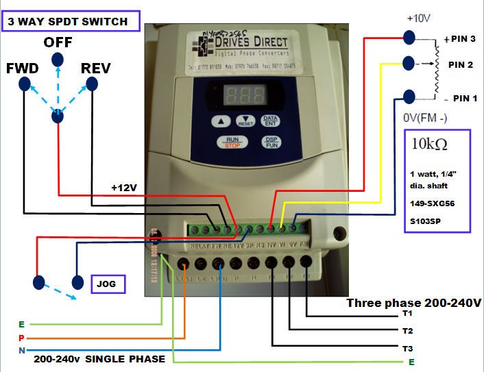
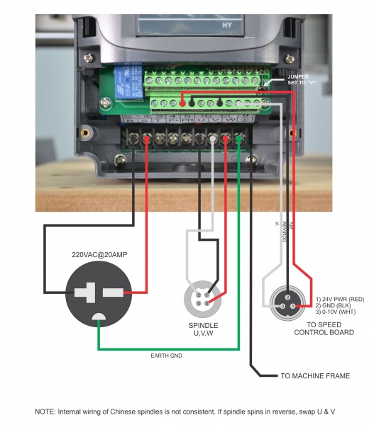
p ups inverter wiring diagrams connection ups inverter wiring diagrams connection how to connect automatic ups inverter to the home supply system a complete note on solar panel installation calculation about no of solar panels batteries rating backup time inverter ups rating load and required watts with circuit diagrams p p automatic ups inverter wiring connection diagram to the home related electrical wiring tutorial ups inverter wiring diagram with auto manual changeover switch system now according to the below ups connection diagram connect an extra wire phase to those appliances where we have already connected phase and neutral wires from power house db i e two wire as phase live as shown in the below fig variable speed drive inverter wiring ac drive china the electric motor should be connected to the output terminals by correct phase sequence if the motor is in the reverse direction then change any two phase of u t1 v t2 w t3 it also can be achieved by setting the ac drive inverter parameters it should be noted that the output terminal can not connect the phase capacitor and surge absorber inverter motor connection diagram hasil pencarian gambar for speed control of 3 phase induction motor inverter m1x series operating instructions be sure to provide the customer with a copy of this manual thank you for purchasing a panasonic inverter be sure to read the instructions thoroughly before attempting to operate the inverter after reading be sure to keep in a safe place for future reference for speed control of 3 phase induction motor inverter m1x series diagram inverter wiring correct inverter wiring in a battery based pv system abstract a diagram shows how to properly wire a charge controller and an inverter into the same battery based pv system technical documentation v01 diagram inverter wiring class ac 3 rated current for the motor rated current note 9 attach surge killers to the magnetic contactor and exciting coil of the relay note 10 in the case the magnetic contactor mc with 2a type auxiliary contacts is used for the control circuit raise the reliability of the contact by using 2a type contacts in parallel connection p p sstandard connection diagramtandard connection diagram to read a wiring diagram initially you need to know just what essential aspects are consisted of in a wiring diagram and which pictorial symbols are made use of to represent them the usual aspects in a wiring diagram are ground power supply cable as well as connection result tools buttons resistors reasoning gateway lights etc rv inverter charger wiring diagram free wiring diagram 06 01 2017 then you can ground the shell of the motor we have to consider the motor design as well is the motor an inverter duty motor or a direct online motor what voltages are the windings set for and does it have a wiring diagram for delta or a wye let me describe one special case of motor connection motor connection with vfd delta or wye gohz com the motor driven by the inverter is a mainly three phase squirrel cage motor and the motor driven by the vector inverter is three phase type motor with encoder which detects a position and speed in addition there is an energy saving drive high efficiency magnetic motor ipm for further energy saving classification by principle of induction inverter school text inverter beginner course always use wiring diagram supplied on motor nameplate for motors with thermal protection single voltage single rotation single voltage reversible rotation dual voltage single rotation split phase motor dual voltage reversible rotation capacitor motor single phase wiring diagrams always use wiring diagram supplied on motor nameplate three phase wiring diagrams p p how to install play store download play store free motor with inverter search motor with inverter


p ups inverter wiring diagrams connection ups inverter wiring diagrams connection how to connect automatic ups inverter to the home supply system a complete note on solar panel installation calculation about no of solar panels batteries rating backup time inverter ups rating load and required watts with circuit diagrams p p automatic ups inverter wiring connection diagram to the home related electrical wiring tutorial ups inverter wiring diagram with auto manual changeover switch system now according to the below ups connection diagram connect an extra wire phase to those appliances where we have already connected phase and neutral wires from power house db i e two wire as phase live as shown in the below fig variable speed drive inverter wiring ac drive china the electric motor should be connected to the output terminals by correct phase sequence if the motor is in the reverse direction then change any two phase of u t1 v t2 w t3 it also can be achieved by setting the ac drive inverter parameters it should be noted that the output terminal can not connect the phase capacitor and surge absorber inverter motor connection diagram hasil pencarian gambar for speed control of 3 phase induction motor inverter m1x series operating instructions be sure to provide the customer with a copy of this manual thank you for purchasing a panasonic inverter be sure to read the instructions thoroughly before attempting to operate the inverter after reading be sure to keep in a safe place for future reference for speed control of 3 phase induction motor inverter m1x series diagram inverter wiring correct inverter wiring in a battery based pv system abstract a diagram shows how to properly wire a charge controller and an inverter into the same battery based pv system technical documentation v01 diagram inverter wiring class ac 3 rated current for the motor rated current note 9 attach surge killers to the magnetic contactor and exciting coil of the relay note 10 in the case the magnetic contactor mc with 2a type auxiliary contacts is used for the control circuit raise the reliability of the contact by using 2a type contacts in parallel connection p p sstandard connection diagramtandard connection diagram to read a wiring diagram initially you need to know just what essential aspects are consisted of in a wiring diagram and which pictorial symbols are made use of to represent them the usual aspects in a wiring diagram are ground power supply cable as well as connection result tools buttons resistors reasoning gateway lights etc rv inverter charger wiring diagram free wiring diagram 06 01 2017 then you can ground the shell of the motor we have to consider the motor design as well is the motor an inverter duty motor or a direct online motor what voltages are the windings set for and does it have a wiring diagram for delta or a wye let me describe one special case of motor connection motor connection with vfd delta or wye gohz com the motor driven by the inverter is a mainly three phase squirrel cage motor and the motor driven by the vector inverter is three phase type motor with encoder which detects a position and speed in addition there is an energy saving drive high efficiency magnetic motor ipm for further energy saving classification by principle of induction inverter school text inverter beginner course always use wiring diagram supplied on motor nameplate for motors with thermal protection single voltage single rotation single voltage reversible rotation dual voltage single rotation split phase motor dual voltage reversible rotation capacitor motor single phase wiring diagrams always use wiring diagram supplied on motor nameplate three phase wiring diagrams p p how to install play store download play store free motor with inverter search motor with inverter


p ups inverter wiring diagrams connection ups inverter wiring diagrams connection how to connect automatic ups inverter to the home supply system a complete note on solar panel installation calculation about no of solar panels batteries rating backup time inverter ups rating load and required watts with circuit diagrams p p automatic ups inverter wiring connection diagram to the home related electrical wiring tutorial ups inverter wiring diagram with auto manual changeover switch system now according to the below ups connection diagram connect an extra wire phase to those appliances where we have already connected phase and neutral wires from power house db i e two wire as phase live as shown in the below fig variable speed drive inverter wiring ac drive china the electric motor should be connected to the output terminals by correct phase sequence if the motor is in the reverse direction then change any two phase of u t1 v t2 w t3 it also can be achieved by setting the ac drive inverter parameters it should be noted that the output terminal can not connect the phase capacitor and surge absorber inverter motor connection diagram hasil pencarian gambar for speed control of 3 phase induction motor inverter m1x series operating instructions be sure to provide the customer with a copy of this manual thank you for purchasing a panasonic inverter be sure to read the instructions thoroughly before attempting to operate the inverter after reading be sure to keep in a safe place for future reference for speed control of 3 phase induction motor inverter m1x series diagram inverter wiring correct inverter wiring in a battery based pv system abstract a diagram shows how to properly wire a charge controller and an inverter into the same battery based pv system technical documentation v01 diagram inverter wiring class ac 3 rated current for the motor rated current note 9 attach surge killers to the magnetic contactor and exciting coil of the relay note 10 in the case the magnetic contactor mc with 2a type auxiliary contacts is used for the control circuit raise the reliability of the contact by using 2a type contacts in parallel connection p p sstandard connection diagramtandard connection diagram to read a wiring diagram initially you need to know just what essential aspects are consisted of in a wiring diagram and which pictorial symbols are made use of to represent them the usual aspects in a wiring diagram are ground power supply cable as well as connection result tools buttons resistors reasoning gateway lights etc rv inverter charger wiring diagram free wiring diagram 06 01 2017 then you can ground the shell of the motor we have to consider the motor design as well is the motor an inverter duty motor or a direct online motor what voltages are the windings set for and does it have a wiring diagram for delta or a wye let me describe one special case of motor connection motor connection with vfd delta or wye gohz com the motor driven by the inverter is a mainly three phase squirrel cage motor and the motor driven by the vector inverter is three phase type motor with encoder which detects a position and speed in addition there is an energy saving drive high efficiency magnetic motor ipm for further energy saving classification by principle of induction inverter school text inverter beginner course always use wiring diagram supplied on motor nameplate for motors with thermal protection single voltage single rotation single voltage reversible rotation dual voltage single rotation split phase motor dual voltage reversible rotation capacitor motor single phase wiring diagrams always use wiring diagram supplied on motor nameplate three phase wiring diagrams p p how to install play store download play store free motor with inverter search motor with inverter
inverter adalah,inverter ac,inverter ac adalah,inverter ac ke dc,inverter aki,inverter ac to dc,inverter abb,inverter artinya,inverter ac ke ac,inverter aki motor,motor aerox,motor adv,motor astrea,motor atv,motor antik,motor adventure,motor aki anak,motor adv 150,motor ac,motor aprilia,connection artinya,connection adalah,connection are available,connection alfamart,connection academy,connection antonym,connections academy login,connection apartments,connection abbreviation,connection at auburn,diagram alir,diagram alir penelitian,diagram adalah,diagram activity,diagram alir adalah,diagram aktivitas,diagram alir proses produksi,diagram analisis swot,diagram arus data,diagram alir data


