inverter circuit diagram explanation


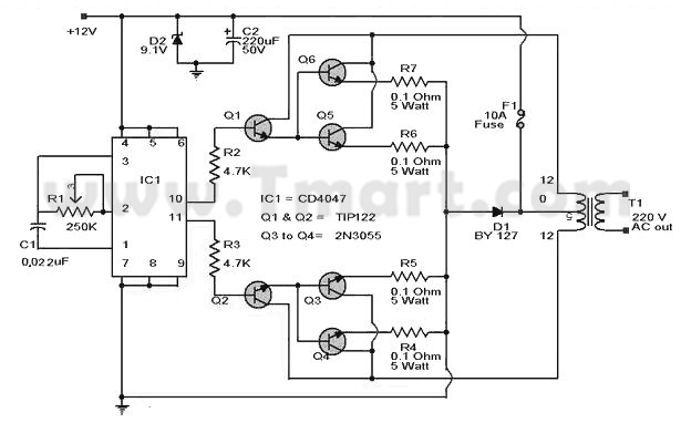
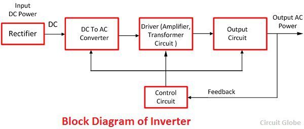
p how does an inverter work schematic and operation explanation of what is an inverter what is its function its schematic diagram what is its working principle and what are the main types of inverters used in photovoltaic stand alone and grid connected systems p p 100 watt 12v dc to 220v ac inverter circuit diagram 24 05 2016 circuit explanation circuit diagram of 100 watt dc to ac inverter has been given below we have used easyeda to draw this circuit diagram and covered a tutorial on how to use easyeda for drawing and simulating the circuits you can also covert this circuit diagram into pcb layout as we have explained in easyeda tutorial and build this how to make 12v dc to 220v ac converter inverter circuit design 21 01 2016 to design a 100 watt inverter read simple 100 watt inverter 12v dc to 220v ac converter circuit using astable multivibrator inverter circuits can either use thyristors as switching devices or transistors normally for low and medium power applications power transistors are used inverter circuit diagram explanation hasil pencarian gambar 20 08 2018 simple inverter using d882 transistor with circuit diagram explanation simple inverter simple inverter using d882 transistor my popular videos 1 how to make powerbank from cfl circuit step simple inverter using d882 transistor with circuit diagram 22 08 2015 simple 100w inverter circuit diagram explanation in the circuit diagram we can observe that 12v battery is connecter to the diode led and also connected to the pin8 of the ic 4047 which is vcc or power supply pin and also to pin 4 and 5 which are astable and complement astable of the ic simple 100w inverter circuit diagram and its working 22 08 2017 inverter an inverter is used to produce an un interrupted 220v ac or 110v ac depending on the line voltage of the particular country supply to the device connected as the load at the output socket the inverter gives constant ac voltage at its output socket when the ac mains power supply is not available lets look how the inverter makes this possible to grasp the functioning of an inverter p p how an inverter works working of inverter with block diagram 15 08 2017 how to make simple low power 12v to 220v inverter simple 150w inverter circuit using cd4047 ic a 100 working circuit using power mosfet and cd4047 the power can be increased using higher rating how to make simple inverter 100 working circuit youtube 27 11 2018 100 watt inverter circuit diagram parts list design tips inverters are devices that convert dc input supply to ac alternating current they are also called power inverters power inverters have numerous applications in power electronics field 100 watt inverter circuit diagram parts list design tips 16 04 2017 pwm pulse width modulation signal based inverters are produce output as pure sine wave and it can be used for any electric appliance that meets the inverter output range simple and powerful pwm inverter circuit diagram designed with ic sg3524 regulating pulse width modulator gives upto 230v ac from 12v dc supply pwm inverter circuit diagram pwm inverter circuit 11 03 2017 share on tumblr inverter circuit gives alternating current ac output from battery power source but the battery requires constant dc supply to get charge so the every inverter circuit contains rectifier and battery charger segment we need to provide ac input power to those circuits then only we can get ac output from inverter circuit when there is no ac supply outlet we couldn t pv solar inverter circuit diagram theorycircuit p p


p how does an inverter work schematic and operation explanation of what is an inverter what is its function its schematic diagram what is its working principle and what are the main types of inverters used in photovoltaic stand alone and grid connected systems p p 100 watt 12v dc to 220v ac inverter circuit diagram 24 05 2016 circuit explanation circuit diagram of 100 watt dc to ac inverter has been given below we have used easyeda to draw this circuit diagram and covered a tutorial on how to use easyeda for drawing and simulating the circuits you can also covert this circuit diagram into pcb layout as we have explained in easyeda tutorial and build this how to make 12v dc to 220v ac converter inverter circuit design 21 01 2016 to design a 100 watt inverter read simple 100 watt inverter 12v dc to 220v ac converter circuit using astable multivibrator inverter circuits can either use thyristors as switching devices or transistors normally for low and medium power applications power transistors are used inverter circuit diagram explanation hasil pencarian gambar 20 08 2018 simple inverter using d882 transistor with circuit diagram explanation simple inverter simple inverter using d882 transistor my popular videos 1 how to make powerbank from cfl circuit step simple inverter using d882 transistor with circuit diagram 22 08 2015 simple 100w inverter circuit diagram explanation in the circuit diagram we can observe that 12v battery is connecter to the diode led and also connected to the pin8 of the ic 4047 which is vcc or power supply pin and also to pin 4 and 5 which are astable and complement astable of the ic simple 100w inverter circuit diagram and its working 22 08 2017 inverter an inverter is used to produce an un interrupted 220v ac or 110v ac depending on the line voltage of the particular country supply to the device connected as the load at the output socket the inverter gives constant ac voltage at its output socket when the ac mains power supply is not available lets look how the inverter makes this possible to grasp the functioning of an inverter p p how an inverter works working of inverter with block diagram 15 08 2017 how to make simple low power 12v to 220v inverter simple 150w inverter circuit using cd4047 ic a 100 working circuit using power mosfet and cd4047 the power can be increased using higher rating how to make simple inverter 100 working circuit youtube 27 11 2018 100 watt inverter circuit diagram parts list design tips inverters are devices that convert dc input supply to ac alternating current they are also called power inverters power inverters have numerous applications in power electronics field 100 watt inverter circuit diagram parts list design tips 16 04 2017 pwm pulse width modulation signal based inverters are produce output as pure sine wave and it can be used for any electric appliance that meets the inverter output range simple and powerful pwm inverter circuit diagram designed with ic sg3524 regulating pulse width modulator gives upto 230v ac from 12v dc supply pwm inverter circuit diagram pwm inverter circuit 11 03 2017 share on tumblr inverter circuit gives alternating current ac output from battery power source but the battery requires constant dc supply to get charge so the every inverter circuit contains rectifier and battery charger segment we need to provide ac input power to those circuits then only we can get ac output from inverter circuit when there is no ac supply outlet we couldn t pv solar inverter circuit diagram theorycircuit p p


p how does an inverter work schematic and operation explanation of what is an inverter what is its function its schematic diagram what is its working principle and what are the main types of inverters used in photovoltaic stand alone and grid connected systems p p 100 watt 12v dc to 220v ac inverter circuit diagram 24 05 2016 circuit explanation circuit diagram of 100 watt dc to ac inverter has been given below we have used easyeda to draw this circuit diagram and covered a tutorial on how to use easyeda for drawing and simulating the circuits you can also covert this circuit diagram into pcb layout as we have explained in easyeda tutorial and build this how to make 12v dc to 220v ac converter inverter circuit design 21 01 2016 to design a 100 watt inverter read simple 100 watt inverter 12v dc to 220v ac converter circuit using astable multivibrator inverter circuits can either use thyristors as switching devices or transistors normally for low and medium power applications power transistors are used inverter circuit diagram explanation hasil pencarian gambar 20 08 2018 simple inverter using d882 transistor with circuit diagram explanation simple inverter simple inverter using d882 transistor my popular videos 1 how to make powerbank from cfl circuit step simple inverter using d882 transistor with circuit diagram 22 08 2015 simple 100w inverter circuit diagram explanation in the circuit diagram we can observe that 12v battery is connecter to the diode led and also connected to the pin8 of the ic 4047 which is vcc or power supply pin and also to pin 4 and 5 which are astable and complement astable of the ic simple 100w inverter circuit diagram and its working 22 08 2017 inverter an inverter is used to produce an un interrupted 220v ac or 110v ac depending on the line voltage of the particular country supply to the device connected as the load at the output socket the inverter gives constant ac voltage at its output socket when the ac mains power supply is not available lets look how the inverter makes this possible to grasp the functioning of an inverter p p how an inverter works working of inverter with block diagram 15 08 2017 how to make simple low power 12v to 220v inverter simple 150w inverter circuit using cd4047 ic a 100 working circuit using power mosfet and cd4047 the power can be increased using higher rating how to make simple inverter 100 working circuit youtube 27 11 2018 100 watt inverter circuit diagram parts list design tips inverters are devices that convert dc input supply to ac alternating current they are also called power inverters power inverters have numerous applications in power electronics field 100 watt inverter circuit diagram parts list design tips 16 04 2017 pwm pulse width modulation signal based inverters are produce output as pure sine wave and it can be used for any electric appliance that meets the inverter output range simple and powerful pwm inverter circuit diagram designed with ic sg3524 regulating pulse width modulator gives upto 230v ac from 12v dc supply pwm inverter circuit diagram pwm inverter circuit 11 03 2017 share on tumblr inverter circuit gives alternating current ac output from battery power source but the battery requires constant dc supply to get charge so the every inverter circuit contains rectifier and battery charger segment we need to provide ac input power to those circuits then only we can get ac output from inverter circuit when there is no ac supply outlet we couldn t pv solar inverter circuit diagram theorycircuit p p
inverter adalah,inverter ac,inverter ac adalah,inverter ac ke dc,inverter aki,inverter ac to dc,inverter abb,inverter artinya,inverter ac ke ac,inverter aki motor,circuit adalah,circuit analysis,circuit and packet switching,circuit app,circuit arcade bar,cricut air 2,circuit apartments,circuit abbreviation,circuit assembly,circuit analysis problems,diagram alir,diagram alir penelitian,diagram adalah,diagram activity,diagram alir adalah,diagram aktivitas,diagram alir proses produksi,diagram analisis swot,diagram arus data,diagram alir data,explanation artinya,explanation adalah,explanation about descriptive text,explanation about rain,explanation about flood,explanation about bullying,explanation about narrative text,explanation about simple present tense,explanation about recount text,explanation about trinity


