Crt Tv Circuit Diagram Free Download: The Ultimate Guide to Understanding and Obtaining the Circuit Diagram
CRT TVs (Cathode Ray Tube televisions) have been an integral part of many households for decades. These classic TVs provided hours of entertainment and served as the primary source of visual media. Understanding the inner workings of a CRT TV can be both fascinating and useful for troubleshooting and repairs.
One essential resource for comprehending the circuitry of a CRT TV is the circuit diagram. This guide will explore the concept of CRT TV circuit diagram free download and provide valuable insights on how to acquire this important document.
Crt Tv Circuit Diagram Free Download
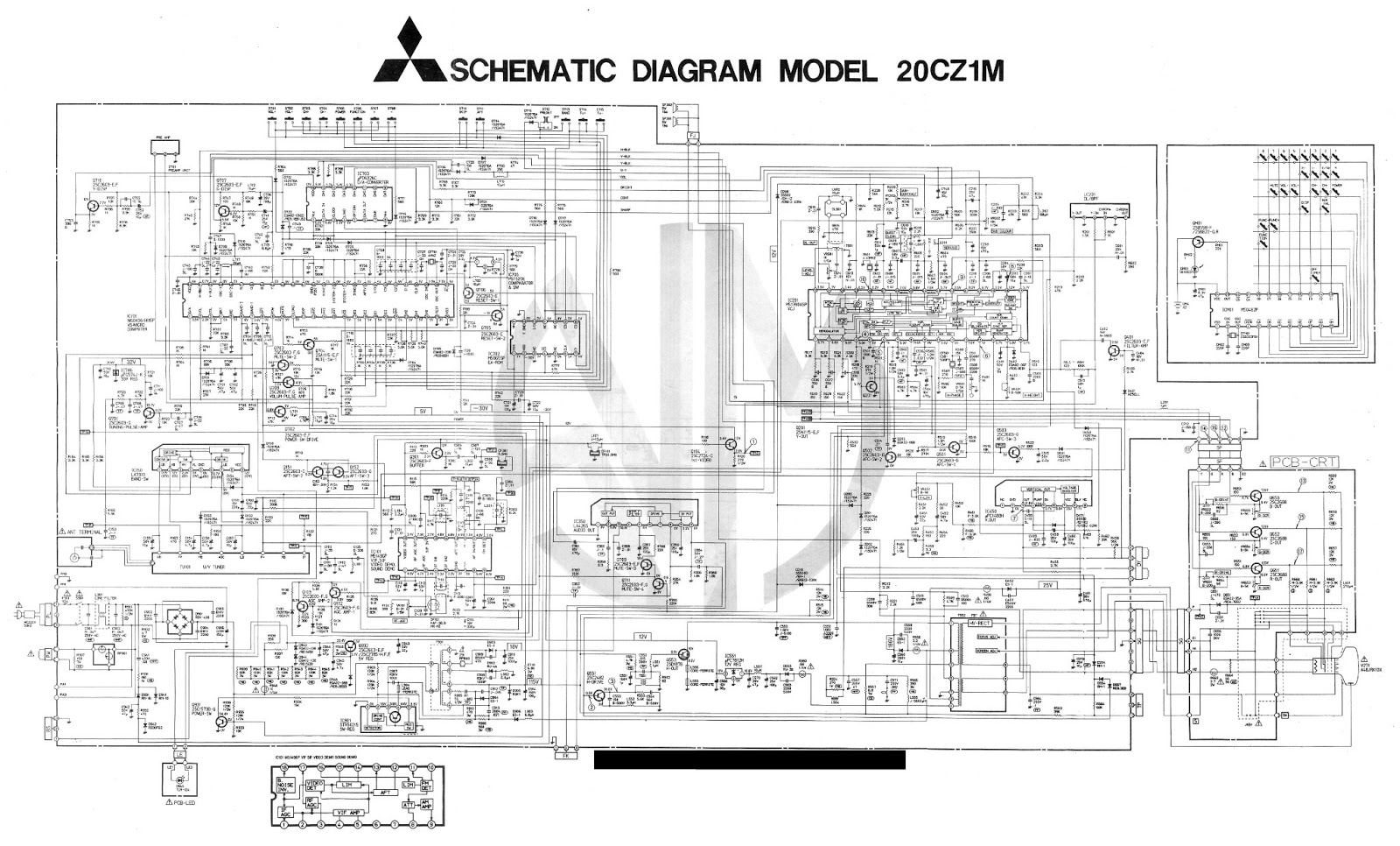
A CRT TV circuit diagram is a graphical representation of the electrical circuitry inside a CRT TV. It provides a detailed overview of the various components, connections, and signals involved in the functioning of the TV. By examining the circuit diagram, technicians and enthusiasts can gain a deeper understanding of how the TV works and pinpoint potential issues.
To obtain a CRT TV circuit diagram for free, there are several online platforms and forums where you can find downloadable resources. These platforms often have a wide selection of circuit diagrams for various CRT TV models, making it easier to find the specific one you need. Additionally, manufacturers' websites and online service manuals can be valuable sources of circuit diagrams.
It's important to note that while many circuit diagrams are available for free, some websites or platforms may require registration or a small fee to access certain diagrams. However, there are still plenty of options available for those seeking a CRT TV circuit diagram free download.
Understanding the Importance of a CRT TV Circuit Diagram
A CRT TV circuit diagram is an invaluable tool for troubleshooting and repairing CRT TVs. Here are a few key reasons why understanding and utilizing the circuit diagram is crucial:
- Identifying components: The circuit diagram helps identify various components within the TV, such as capacitors, resistors, transistors, and integrated circuits. This knowledge allows technicians to locate and test specific parts during repairs.
- Analyzing connections: The circuit diagram illustrates the interconnections between different components and helps technicians understand the flow of electrical signals. This understanding is vital for diagnosing faults and ensuring proper functionality.
- Diagnosing issues: When a CRT TV malfunctions, the circuit diagram serves as a roadmap for troubleshooting. Technicians can trace the path of signals, identify faulty components or connections, and pinpoint the root cause of the issue.
- Modifying and upgrading: Circuit diagrams enable enthusiasts to modify or upgrade their CRT TVs. By studying the existing circuitry, they can add new features, enhance picture quality, or improve audio performance, unleashing their creativity and technical skills.
How to Obtain a CRT TV Circuit Diagram
Obtaining a CRT TV circuit diagram is now easier than ever, thanks to the availability of online resources. Here's a step-by-step guide on how to obtain a CRT TV circuit diagram:
- Search online platforms: Start by exploring dedicated websites, forums, and communities that offer free circuit diagrams. Use search engines and relevant keywords like "CRT TV circuit diagram free download" to narrow down your options.
- Visit manufacturer websites: Some CRT TV manufacturers provide circuit diagrams for their models on their official websites or through online service manuals. Look for the support or downloads section on the manufacturer's website to find the desired diagram.
- Online service manuals: Numerous websites provide service manuals for various CRT TV models, which often include the circuit diagram. These manuals can be a valuable resource, providing detailed information on troubleshooting, repairs, and circuit diagrams.
- Consider forums and communities: Engage with online communities, forums, or social media groups dedicated to CRT TV repairs and enthusiasts. These platforms often have members willing to share circuit diagrams or provide guidance on where to find them.
- Contributing to the community: If you have access to a CRT TV circuit diagram that is not readily available online, consider sharing it with the community. This act of contribution helps expand the database of circuit diagrams and benefits others with similar interests.
Remember to always respect copyright laws and intellectual property rights when accessing and sharing circuit diagrams.
The Components of a CRT TV Circuit Diagram
A CRT TV circuit diagram consists of various components that work together to produce the desired output. Understanding these components and their functions is essential for comprehending the circuit diagram. Here are some key components typically found in a CRT TV circuit:
- Power supply circuit: This circuit provides the necessary voltage and current to power the different sections of the TV.
- Horizontal and vertical deflection circuit: Responsible for scanning the electron beam across the screen horizontally and vertically to create the image.
- Video and audio circuits: These circuits process the incoming video and audio signals, amplify them, and deliver them to the picture tube and speakers, respectively.
- Tuner and IF (Intermediate Frequency) circuits: These circuits receive and process the TV broadcast signals, converting them into video and audio signals for further processing.
- Control and microcontroller circuits: Control circuits manage various functions of the TV, such as volume, channel selection, and menu options. Microcontroller circuits provide intelligent control and interaction with the user.
By studying the circuit diagram and familiarizing yourself with these components, you'll be better equipped to troubleshoot and repair CRT TVs.
Analyzing the Power Supply Circuit
The power supply circuit is one of the fundamental sections of a CRT TV circuit diagram. It ensures that the TV receives a stable and regulated power supply for all its components to function correctly. Understanding this circuit is crucial for diagnosing power-related issues. Let's take a closer look at the different elements within the power supply circuit:
- Transformer: The transformer in the power supply circuit steps down the high voltage from the AC mains to a lower voltage suitable for the TV's internal circuits.
- Rectifier: The rectifier circuit converts the AC voltage from the transformer into DC voltage, which is required by most electronic components in the TV.
- Filter capacitors: These capacitors smooth out the rectified DC voltage, reducing any ripple or fluctuations and ensuring a steady supply of power.
- Voltage regulators: Voltage regulators maintain a constant voltage output, regardless of input voltage fluctuations. They play a critical role in supplying regulated voltages to various sections of the TV.
- Protection components: The power supply circuit may include protective components such as fuses, surge protectors, or voltage regulators to safeguard the TV from power surges or other electrical anomalies.
- Analyzing the power supply circuit allows technicians to identify faulty components, test voltage levels, and rectify issues related to power supply, such as low or no power, flickering screen, or abnormal behavior.
Decoding the Horizontal and Vertical Deflection Circuit
The horizontal and vertical deflection circuits in a CRT TV control the movement of the electron beam across the screen, resulting in the creation of the image. Understanding these circuits is crucial for troubleshooting issues related to screen flickering, distorted images, or lack of synchronization. Let's explore the key elements of the horizontal and vertical deflection circuits:
- Horizontal deflection coil: This coil generates a magnetic field that moves the electron beam horizontally across the screen during each scan line.
- Horizontal output transistor: The horizontal output transistor amplifies the horizontal deflection signals and drives the horizontal deflection coil.
- Horizontal flyback transformer: The flyback transformer generates the high voltage required for the CRT's anode, as well as providing the horizontal deflection signals.
- Vertical deflection coil: The vertical deflection coil controls the movement of the electron beam vertically, allowing the creation of multiple scan lines to form a complete image.
- Vertical output IC: The vertical output integrated circuit amplifies the vertical deflection signals and drives the vertical deflection coil.
Issues in the horizontal and vertical deflection circuits can lead to distorted or rolling images, horizontal or vertical lines on the screen, or no display at all. By examining the circuit diagram and troubleshooting these sections, technicians can rectify these issues effectively.
Examining the Video and Audio Circuits
The video and audio circuits of a CRT TV are responsible for processing and delivering the visual and auditory signals. Understanding these circuits is vital for diagnosing problems related to picture quality, color distortion, or audio abnormalities. Let's delve into the key components of the video and audio circuits:
- Video amplifier: The video amplifier circuit amplifies the video signal received from the tuner or other video sources and prepares it for display on the CRT.
- Video processor: The video processor circuit enhances the video signal, adjusting parameters such as brightness, contrast, color, and sharpness.
- Chroma circuit: The chroma circuit processes the color information in the video signal, ensuring accurate reproduction of colors on the screen.
- Sound IF (Intermediate Frequency) circuit: The sound IF circuit processes the audio signal received from the tuner or external audio sources, converting it into a suitable format for amplification.
- Audio amplifier: The audio amplifier circuit amplifies the processed audio signal and delivers it to the speakers for sound reproduction.
Issues in the video and audio circuits can manifest as poor picture quality, color bleeding, distorted or no sound, or issues with external audio connections. By referring to the circuit diagram and examining these sections, technicians can diagnose and resolve these problems effectively.
Troubleshooting Common Issues Using the Circuit Diagram
The circuit diagram of a CRT TV is an indispensable tool for troubleshooting and resolving common issues that may arise during its lifespan. Here are a few examples of common problems and how the circuit diagram can assist in their resolution:
- No power: If the TV fails to power on, the circuit diagram can help identify faulty components in the power supply circuit, such as fuses, rectifiers, or capacitors, that may be causing the issue.
- Flickering screen: A flickering screen may indicate problems in the horizontal or vertical deflection circuits. The circuit diagram can aid in locating faulty components like transistors, coils, or flyback transformers that need to be replaced.
- Distorted image: Issues such as stretched or compressed images, color distortion, or geometric abnormalities can be traced back to the video and signal processing circuits. The circuit diagram allows technicians to analyze the relevant sections and identify the faulty components or connections.
- No sound: When there is no sound or distorted audio, the audio amplifier circuit or external audio connections may be at fault. By referencing the circuit diagram, technicians can isolate the problematic area and address the issue accordingly.
Intermittent issues: Intermittent problems can be particularly challenging to diagnose. However, with the circuit diagram in hand, technicians can carefully trace the signal paths, identify potential loose connections or components, and rectify the intermittent behavior.
By utilizing the circuit diagram as a roadmap, technicians can troubleshoot CRT TVs more effectively, saving time and ensuring accurate repairs.
Frequently Asked Questions (FAQs)
Can I find a CRT TV circuit diagram for free?
Yes, there are various online platforms, forums, and communities where you can find free CRT TV circuit diagrams. Conduct a thorough search using relevant keywords to locate the desired diagram.
Are circuit diagrams available for different CRT TV models?
Yes, circuit diagrams are available for a wide range of CRT TV models. Manufacturers' websites, online service manuals, and dedicated forums are excellent sources to find specific diagrams for different models.
What software can I use to view and analyze a circuit diagram?
Popular software applications like Adobe Acrobat Reader, Autodesk Eagle, or KiCad can be used to view and analyze circuit diagrams. These programs allow zooming, highlighting, and measuring components for a more in-depth analysis.
Can a circuit diagram help me repair a malfunctioning CRT TV?
Absolutely! A circuit diagram provides valuable insights into the internal workings of a CRT TV. By following the circuit paths and understanding component functions, you can troubleshoot and repair various issues effectively.
Are there any safety precautions I should take when working with a CRT TV circuit diagram?
When working with CRT TV circuit diagrams or performing repairs, always ensure the TV is disconnected from the power source. Additionally, follow proper safety procedures, such as discharging capacitors and avoiding direct contact with high-voltage components.
How can I contribute to the CRT TV circuit diagram database?
If you have access to a circuit diagram that is not readily available online, consider sharing it with the community. You can contribute by uploading the diagram to online platforms, forums, or dedicated websites, thereby expanding the database and assisting others in their repairs.
Conclusion
Understanding the CRT TV circuit diagram is an invaluable skill for technicians, enthusiasts, and anyone interested in the inner workings of these classic televisions. With a CRT TV circuit diagram free download, you can dive into the world of circuitry, troubleshoot issues, and bring new life to these nostalgic devices.
By exploring various online platforms, manufacturers' websites, and communities, you can easily obtain the circuit diagram you need. Remember to respect copyright and intellectual property rights, and consider contributing to the community by sharing any unique circuit diagrams you may possess.
So, grab your CRT TV circuit diagram, roll up your sleeves, and embark on a journey of discovery, repairs, and upgrades. Unleash your technical prowess and keep the magic of CRT TVs alive!
crt tv circuit diagram free download


n a

n a
n a


