inverter circuit diagram with pwm

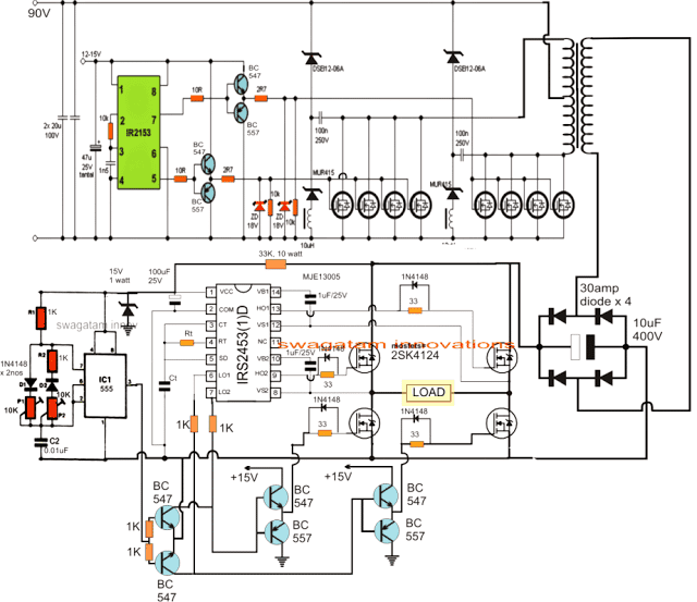


p pwm inverter circuit 16 04 2017 pwm pulse width modulation signal based inverters are produce output as pure sine wave and it can be used for any electric appliance that meets the inverter output range simple and powerful pwm inverter circuit diagram designed with ic sg3524 regulating pulse width modulator gives upto 230v ac from 12v dc supply pwm inverter circuit diagram p p pwm inverter electroschematics com in order to increase the efficiency of the pwm inverter the electronic circuit is highly sophisticated with battery charge sensor ac mains sensor soft start facility output control etc the pwm controller circuit uses pwm ic ka 3225 or lm 494 these ics have internal circuits for the entire operation of the pulse width modulation simple pwm inverter circuit diagram using pwm chip sg3524 04 09 2012 here is a simple pwm dc to ac voltage inverter circuit based on ic sg 3524 the sg3524 ic chips is a fixed frequency pwm pulse width modulation voltage regulator control circuit with indifferent outputs for single ended or push pull applications inverter circuit diagram with pwm hasil pencarian gambar 250w pwm inverter circuit sg3524 a 250w pwm inverter circuit built around ic sg3524 is shown here sg3524 is an integrated switching regulator circuit that has all essential circuitry required for making a switching regulator in single ended or push pull mode pwm inverter circuit based on sg3524 12v input 220v output 11 10 2017 the main feature of this inverter is this is a pwm based circuit and output voltage stables at any load same thing that happens to smps pwm inverter circuit diagram parts list i c sg3524 x1 15 total 12 pcs resistor 6 pwm inverter circuit 500 watt low cost circuits diy 04 07 2012 simple low power inverter circuit 12v dc to 230v or 110v ac diagram using cd4047 and irfz44 power mosfet gallery of electronic circuits and projects providing lot of diy circuit diagrams robotics microcontroller projects electronic development tools p p simple low power inverter circuit 12v dc to 230v or 110v ac 28 11 2019 the working of the inverter can be understood from the following explanation circuit operation as can be seen two ic 4017 are cascaded to form an 18 pin sequencing logic circuit wherein the each negative pulse or frequency from the ic 555 produces a shifting output sequence across each of the indicated outputs of the two 4017 ics starting from pin 9 of the upper ic upto pin 2 of the lower 1500 watt pwm sinewave inverter circuit homemade circuit modulation mode of pwm control circuit a carrier ratio is defined in the 3 phase pwm power inverter circuit the ratio of the carrier frequency fc and the modulated signal fr called the carrier frequency ratio that is n fc fr 3 phase pwm power inverter circuit 250 to 5000 watts pwm dc ac 220v power inverter this is a heavy duty design of a pulse width modulator dc ac inverter using the chip sg3524 i ve been using it as a backup to power up all my house when outages occur since aprox 6 years non stop if you like the work and intend to build the c 250 to 5000 watts pwm dc ac 220v power inverter instructables homemade 2000w power inverter with circuit diagrams thursday october 8 2015 few days ago gohz made a 24v 2000w power inverter in home sharing some design schematics and circuit diagrams homemade 2000w power inverter with circuit diagrams gohz com p p
p pwm inverter circuit 16 04 2017 pwm pulse width modulation signal based inverters are produce output as pure sine wave and it can be used for any electric appliance that meets the inverter output range simple and powerful pwm inverter circuit diagram designed with ic sg3524 regulating pulse width modulator gives upto 230v ac from 12v dc supply pwm inverter circuit diagram p p pwm inverter electroschematics com in order to increase the efficiency of the pwm inverter the electronic circuit is highly sophisticated with battery charge sensor ac mains sensor soft start facility output control etc the pwm controller circuit uses pwm ic ka 3225 or lm 494 these ics have internal circuits for the entire operation of the pulse width modulation simple pwm inverter circuit diagram using pwm chip sg3524 04 09 2012 here is a simple pwm dc to ac voltage inverter circuit based on ic sg 3524 the sg3524 ic chips is a fixed frequency pwm pulse width modulation voltage regulator control circuit with indifferent outputs for single ended or push pull applications inverter circuit diagram with pwm hasil pencarian gambar 250w pwm inverter circuit sg3524 a 250w pwm inverter circuit built around ic sg3524 is shown here sg3524 is an integrated switching regulator circuit that has all essential circuitry required for making a switching regulator in single ended or push pull mode pwm inverter circuit based on sg3524 12v input 220v output 11 10 2017 the main feature of this inverter is this is a pwm based circuit and output voltage stables at any load same thing that happens to smps pwm inverter circuit diagram parts list i c sg3524 x1 15 total 12 pcs resistor 6 pwm inverter circuit 500 watt low cost circuits diy 04 07 2012 simple low power inverter circuit 12v dc to 230v or 110v ac diagram using cd4047 and irfz44 power mosfet gallery of electronic circuits and projects providing lot of diy circuit diagrams robotics microcontroller projects electronic development tools p p simple low power inverter circuit 12v dc to 230v or 110v ac 28 11 2019 the working of the inverter can be understood from the following explanation circuit operation as can be seen two ic 4017 are cascaded to form an 18 pin sequencing logic circuit wherein the each negative pulse or frequency from the ic 555 produces a shifting output sequence across each of the indicated outputs of the two 4017 ics starting from pin 9 of the upper ic upto pin 2 of the lower 1500 watt pwm sinewave inverter circuit homemade circuit modulation mode of pwm control circuit a carrier ratio is defined in the 3 phase pwm power inverter circuit the ratio of the carrier frequency fc and the modulated signal fr called the carrier frequency ratio that is n fc fr 3 phase pwm power inverter circuit 250 to 5000 watts pwm dc ac 220v power inverter this is a heavy duty design of a pulse width modulator dc ac inverter using the chip sg3524 i ve been using it as a backup to power up all my house when outages occur since aprox 6 years non stop if you like the work and intend to build the c 250 to 5000 watts pwm dc ac 220v power inverter instructables homemade 2000w power inverter with circuit diagrams thursday october 8 2015 few days ago gohz made a 24v 2000w power inverter in home sharing some design schematics and circuit diagrams homemade 2000w power inverter with circuit diagrams gohz com p p
p pwm inverter circuit 16 04 2017 pwm pulse width modulation signal based inverters are produce output as pure sine wave and it can be used for any electric appliance that meets the inverter output range simple and powerful pwm inverter circuit diagram designed with ic sg3524 regulating pulse width modulator gives upto 230v ac from 12v dc supply pwm inverter circuit diagram p p pwm inverter electroschematics com in order to increase the efficiency of the pwm inverter the electronic circuit is highly sophisticated with battery charge sensor ac mains sensor soft start facility output control etc the pwm controller circuit uses pwm ic ka 3225 or lm 494 these ics have internal circuits for the entire operation of the pulse width modulation simple pwm inverter circuit diagram using pwm chip sg3524 04 09 2012 here is a simple pwm dc to ac voltage inverter circuit based on ic sg 3524 the sg3524 ic chips is a fixed frequency pwm pulse width modulation voltage regulator control circuit with indifferent outputs for single ended or push pull applications inverter circuit diagram with pwm hasil pencarian gambar 250w pwm inverter circuit sg3524 a 250w pwm inverter circuit built around ic sg3524 is shown here sg3524 is an integrated switching regulator circuit that has all essential circuitry required for making a switching regulator in single ended or push pull mode pwm inverter circuit based on sg3524 12v input 220v output 11 10 2017 the main feature of this inverter is this is a pwm based circuit and output voltage stables at any load same thing that happens to smps pwm inverter circuit diagram parts list i c sg3524 x1 15 total 12 pcs resistor 6 pwm inverter circuit 500 watt low cost circuits diy 04 07 2012 simple low power inverter circuit 12v dc to 230v or 110v ac diagram using cd4047 and irfz44 power mosfet gallery of electronic circuits and projects providing lot of diy circuit diagrams robotics microcontroller projects electronic development tools p p simple low power inverter circuit 12v dc to 230v or 110v ac 28 11 2019 the working of the inverter can be understood from the following explanation circuit operation as can be seen two ic 4017 are cascaded to form an 18 pin sequencing logic circuit wherein the each negative pulse or frequency from the ic 555 produces a shifting output sequence across each of the indicated outputs of the two 4017 ics starting from pin 9 of the upper ic upto pin 2 of the lower 1500 watt pwm sinewave inverter circuit homemade circuit modulation mode of pwm control circuit a carrier ratio is defined in the 3 phase pwm power inverter circuit the ratio of the carrier frequency fc and the modulated signal fr called the carrier frequency ratio that is n fc fr 3 phase pwm power inverter circuit 250 to 5000 watts pwm dc ac 220v power inverter this is a heavy duty design of a pulse width modulator dc ac inverter using the chip sg3524 i ve been using it as a backup to power up all my house when outages occur since aprox 6 years non stop if you like the work and intend to build the c 250 to 5000 watts pwm dc ac 220v power inverter instructables homemade 2000w power inverter with circuit diagrams thursday october 8 2015 few days ago gohz made a 24v 2000w power inverter in home sharing some design schematics and circuit diagrams homemade 2000w power inverter with circuit diagrams gohz com p p
inverter adalah,inverter ac,inverter ac adalah,inverter ac ke dc,inverter aki,inverter ac to dc,inverter abb,inverter artinya,inverter ac ke ac,inverter aki motor,circuit adalah,circuit analysis,circuit and packet switching,circuit app,circuit arcade bar,cricut air 2,circuit apartments,circuit abbreviation,circuit assembly,circuit analysis problems,diagram alir,diagram alir penelitian,diagram adalah,diagram activity,diagram alir adalah,diagram aktivitas,diagram alir proses produksi,diagram analisis swot,diagram arus data,diagram alir data,with all i am,with all i am lyrics,with artinya,with all i am chord,with all due respect,with arms wide open,with a grain of salt,with all due respect meaning,with all my heart,with a little help from my friends lyrics,pwm adalah,pwm arduino,pwm arduino adalah,pwm arduino nano,pwm arduino code,pwm adalah pdf,pwm arduino mega,pwm atmega8535,pwm arduino frequency,pwm ac


