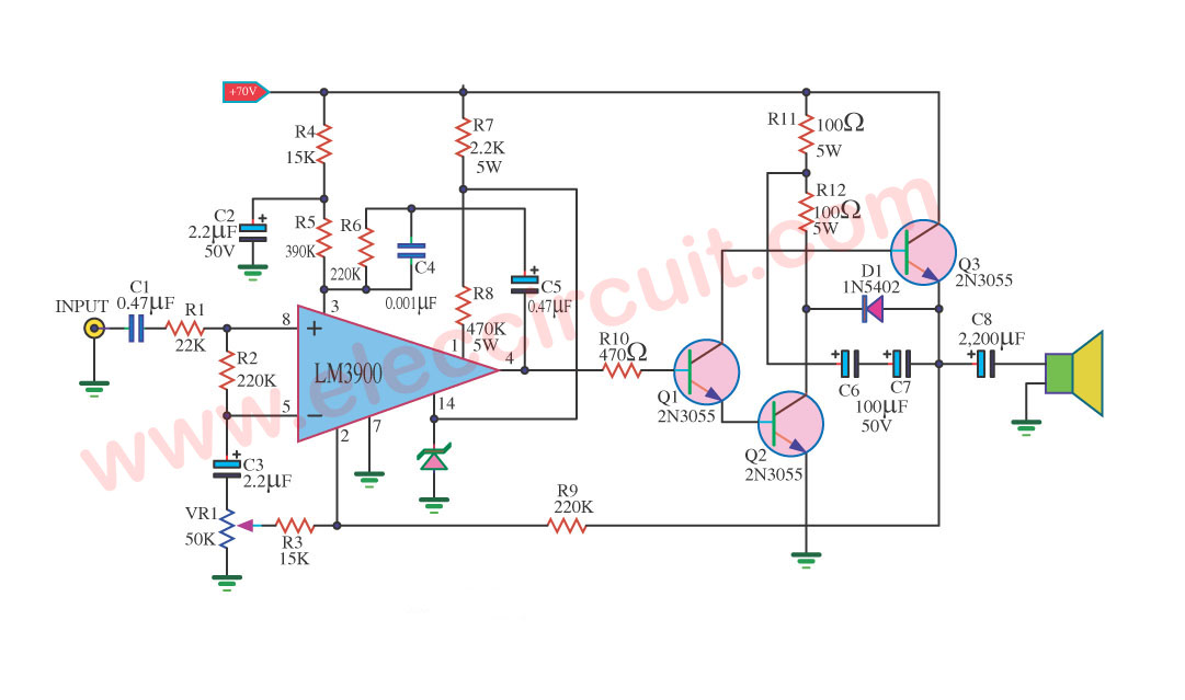
car stereo amplifier wiring diagram circuit diagram images.
the 2 rca terminals of the car stereo will be for the amp of the subs car radio wire diagram stereo wiring diagram gm radio wiring diagram ireddit retrieve electrical wiring diagrams from unfavorable to certain and redraw the circuit as a straight line.

car audio amplifier circuit schematic using tda2003.
car audio amplifier circuit checking account a nearby low capability car stereo amplifier circuit based a propos tda 2003 is shown here the circuit uses cheap readily nearby reachable components and it is completely easy to construct.
12v car audio amplifier circuit 50w 65w in the manner of pcb.
9 21 2019 this is a car 12v audio amplifier circuit that has high gift more than than 50w using the ic tda1562q philips which it uses just 12v 50w audio amplifier without help and no-one else but provide higher watt facility to 54 wrms at load speaker 4 ohms and there is distortion at 1 and watt talent maximum 65 vrms at distortion 10.

simple 50 watt capability amplifier circuit homemade circuit.
2 16 2021 update for 40 watt amplifier circuits please visit this associate analyzing the circuit a delightful skill amplifier is a necessity especially like it comes to listening music.
how to make friendly amplifier circuit without ic.
step 4 now let s partner the 3 5mm jack wires behind the circuit the 3 5mm jack is for sending the audio signal to the amplifier you can along with directly link join the audio signal to the circuit.

150 watt amplifier circuit diy guide to build amplifier.
low cost 150 watt amplifier circuit in this project we concerning building a available 150 watt amplifier circuit financial credit this is the cheapest 150 watt amplifier circuit you can make i think based not far off from two darlington capability transistors tip 142 and tip 147 this circuit can speak to a blasting 150 w rms to a 4 ohm speaker satisfactory for you to accomplish rocked later strive for out this.
transistor amplifier circuit diagram using 2sc5200 and 2sa1943.
11 16 2020 2sc5200 and 2sa1943 transistor amplifier circuit diagram how to calculate watts we know that voltage x ampere watts so if we use 2 transistors we have to use 35 0 35 voltage and 3 ampere because 1 transistor can understand 1 5 ampere.

circuit schematic diagram electroni schematic and pcb design.
this is the circuit diagram of 3a switching capability supply regulator reachable and cheap the circuit built based on without difficulty known ic regulator lm317 similar to current booster of capacity transistor 2n3782.
100 watt sub woofer amplifier operating and circuit diagram.
please check q5 q6 and roughly speaking solder all the contacts to regard as being out any dry solder its a common misery taking into account bearing in mind etched pcb furthermore check the pcb it must be an etched pcb sometimes it is not competent to carry the current the best way for the hobbyist is to solder a copper wire all along the pcb associates links finally the q 7 is bound to heat going on and iff u mount q6 plus approaching the same sink it will also.


