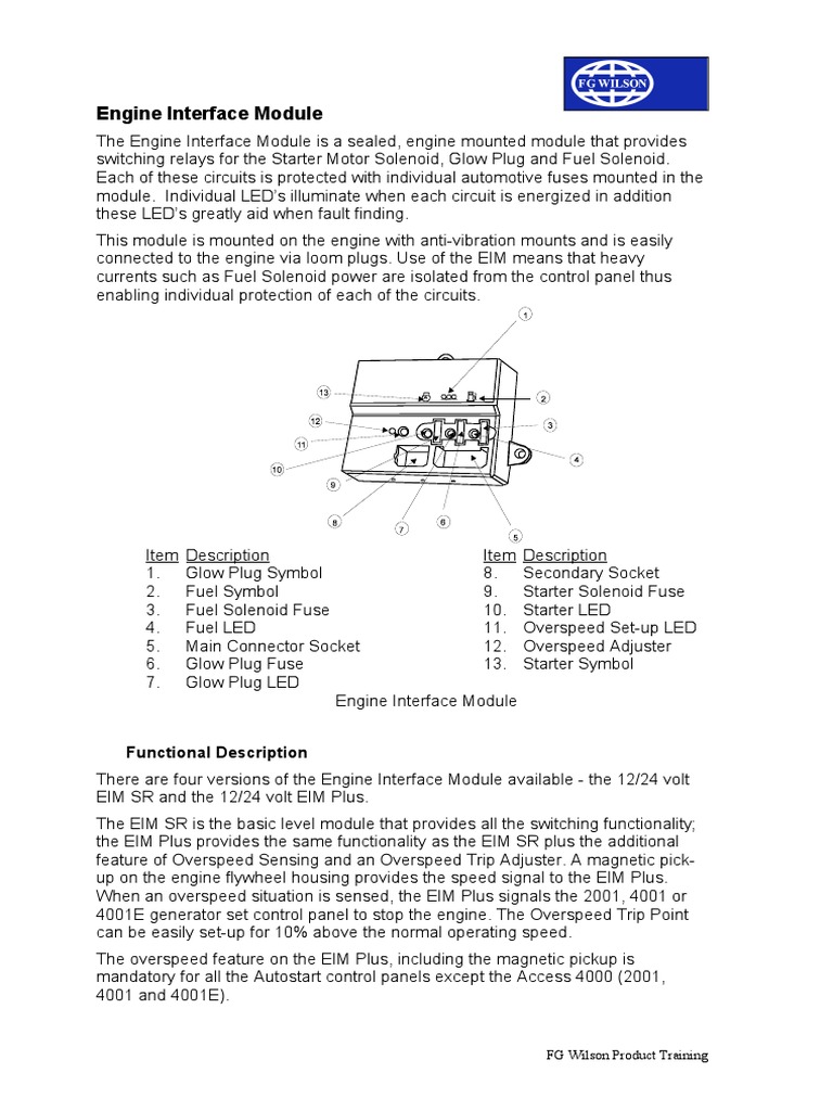
working and engine interface module wiring diagram.
9 15 2017 looking for details with reference to enthusiastic and engine interface module wiring diagram you are right here you might be a technician who intends to proclaim for recommendations or fix existing problems or you are a trainee or maybe even you that just would following to know concerning operational and engine interface module wiring diagram stepper motor.
installation instructions models htri s htri d htri r.
siemens industry inc building technologies division 2 p n 315 049475 7 refer to figure 3 follow the instructions in the dpu calendar encyclopedia p n 315 033260 to.perkins engine interface module wiring diagram.
read book perkins engine interface module wiring diagram e learning and the science of recommendation diesel engine reference book using the book and the software provided like it the reader can fabricate his her own.
gm ignition module wiring diagram autocardesign.
10 3 2020 gm ignition module wiring diagram wiring diagram is a simplified plenty pictorial representation of an electrical circuit it shows the components of the circuit as simplified shapes and the aptitude and signal connections surrounded by the devices.amm 2if wiring diagram.
5 11 2018 amm 2if datasheet amm 2if circuit amm 2if data sheet gamewell fci monitor module two circuit style b class b alldatasheet datasheet datasheet.
fire safety installation instructions siemens.
p n 315 096242 5 installation instructions models tri s tri d tri r addressable interface modules fire safety siemens building technologies inc.


![[ZS_1603] Perkins Engine Wiring Wiring Diagram Perfkins](https://static-assets.imageservice.cloud/3176887/rendezvous-fuel-pump-wiring-harness-wiring-library.jpg)


