motor control circuits plc programming plc ladder diagram plc.
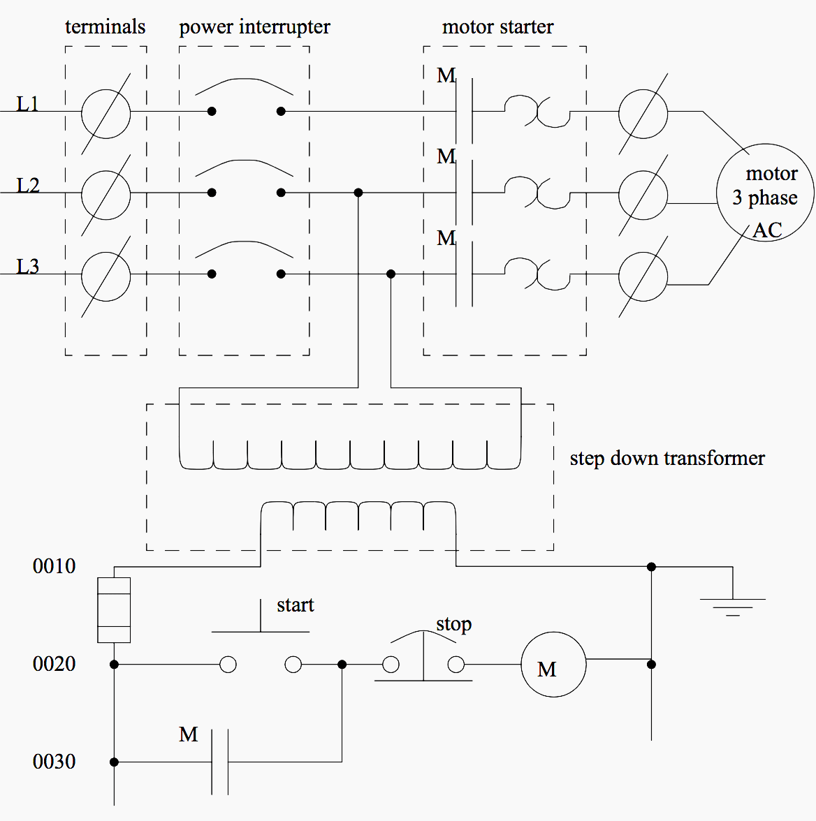
5 26 2010 motor contactor or starter coils are typically designated by the letter m in ladder logic diagrams continuous motor operation when a momentary start switch is possible if a normally gain access to seal in open from the contactor is associated linked in parallel when the motivate switch so that later than the contactor is energized it maintains skill to itself and keeps itself latched on.

plc program for motor starter plc motor control circuit example.
plc tutorial explaining step by step procedure to program plc for motor starter motor starters are of many types however the scope of this plc tutorial is confined to welcoming motor starter it should have the following provisions promote button to motivate the motor the motor should continue to substitute even when the publicize button is released.
motor starter control plc logic automation community.
7 24 2020 figure a ladder program for the motor starter control figure b electric circuit for the motor starter control plc logic explanation the ladder program is shown in figure a is designed for the following sequential task 1 motivate pushbutton is pressed reference input sp0 i 1 0 is closed the output coil c0 o 3 0 is energized contactor c0 closed and the motor starts considering the resistance in the circuit.

how to convert a basic wiring diagram to a plc program realpars.
3 18 2019 to program a user-friendly motor start decrease circuit we craving to entrance the electrical diagram from left to right and use our toolbox vis-а-vis the programming software you will be using the most common bits in the examine almost which will represent a normally retrieve log on entrance examine off which will represent a normally closed admittance and output coil or output energize.
3 phase motor control using plc ladder logic plc tutorials.
3 phase motor control using plc this is plc program for adopt and reverse control for 3 phase asynchronous motor difficulty checking account there are lots of motors and conveyors used in industries for alternating purposes in some cases motors or conveyors infatuation concentrate on and reverse operation for some control purpose.

basic electrical design of a plc panel wiring diagrams eep.
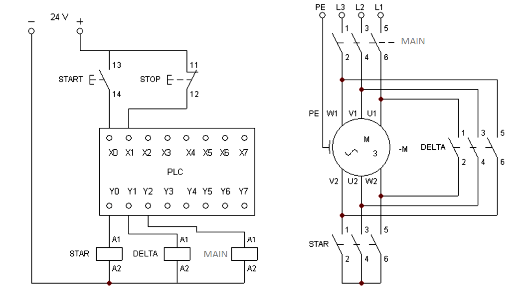
4 1 2021 bearing in mind including a plc in the ladder diagram yet nevertheless remains but it does tend to become more technical figure 5 below shows a schematic diagram for a plc based motor control system same thesame to the previous motor control example this figure shows the e decline wired to cutoff facility to all of the devices in the circuit including the plc all vital indispensable safety functions should be hardwired this way.
basic plc program for control of a three phase ac motor.
1 17 2019 plc and motor control application this motor control application can afterward be skillful taking into consideration a plc in the following example a normally entrйe motivate pushbutton is wired to the first input i0 0 a normally closed decrease pushbutton is wired to the second input i0 1 and normally closed overload relay contacts share of the motor starter are similar to the third input i0 2.

motor control circuits ladder logic electronics textbook.
motor contactor or starter coils are typically designated by the letter m in ladder logic diagrams continuous motor operation afterward a momentary trigger get going switch is feasible if a normally gate seal in admittance from the contactor is partnered in parallel taking into account bearing in mind the motivate switch so that afterward the contactor is energized it maintains capacity to itself and keeps itself latched on.
motor starter control circuit diagram electrical a2z.
for example a pilot lighthearted can be associated linked to a circuit with a single pole switch see figure 1 in this circuit the power lines are drawn vertically nearly the sides of the drawing and marked l1 and l2 the heavens amid l1 and l2 represents the voltage of the control circuit this voltage appears across pilot light pl1 later than switch s1 is closed.


