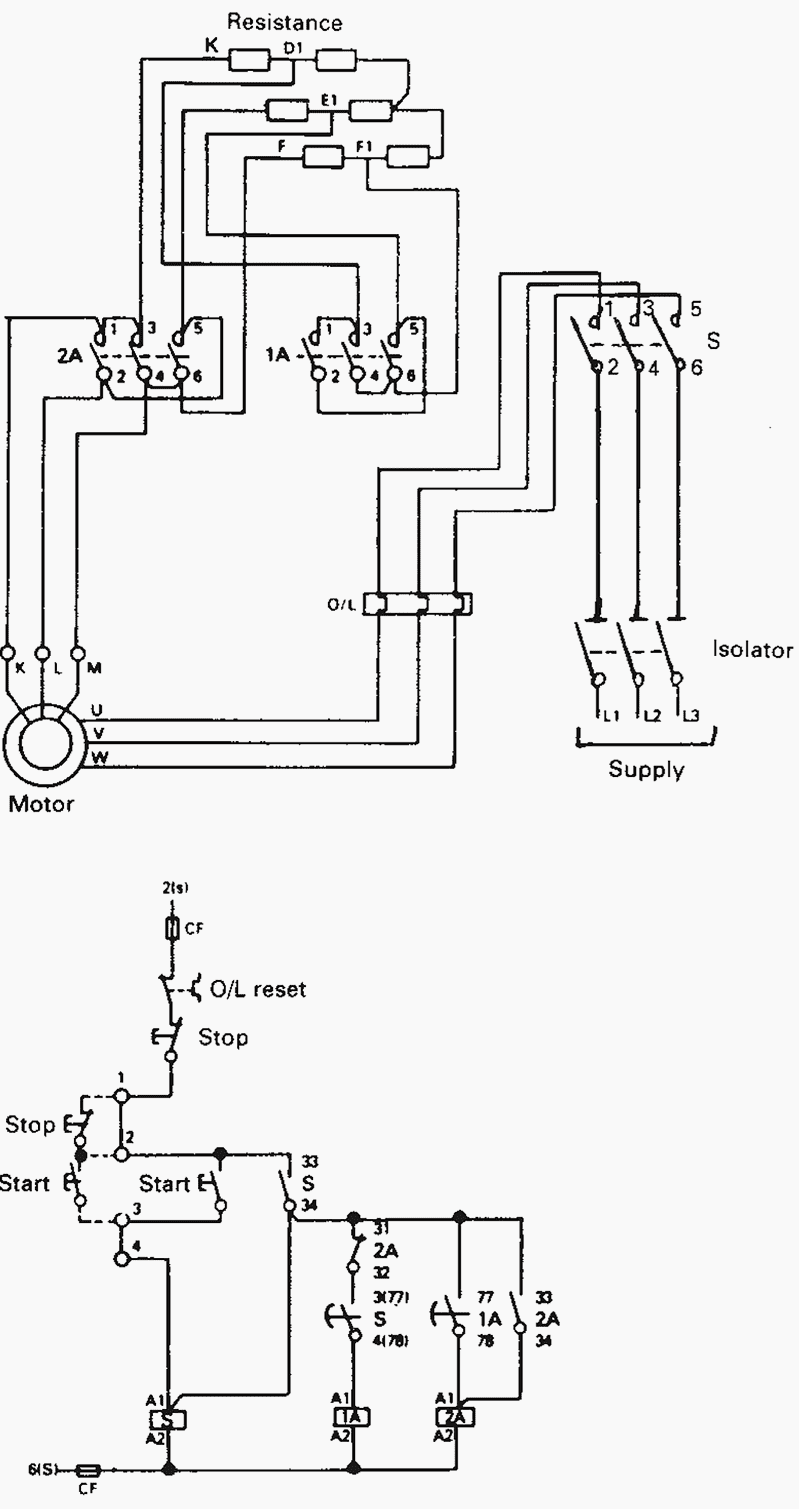
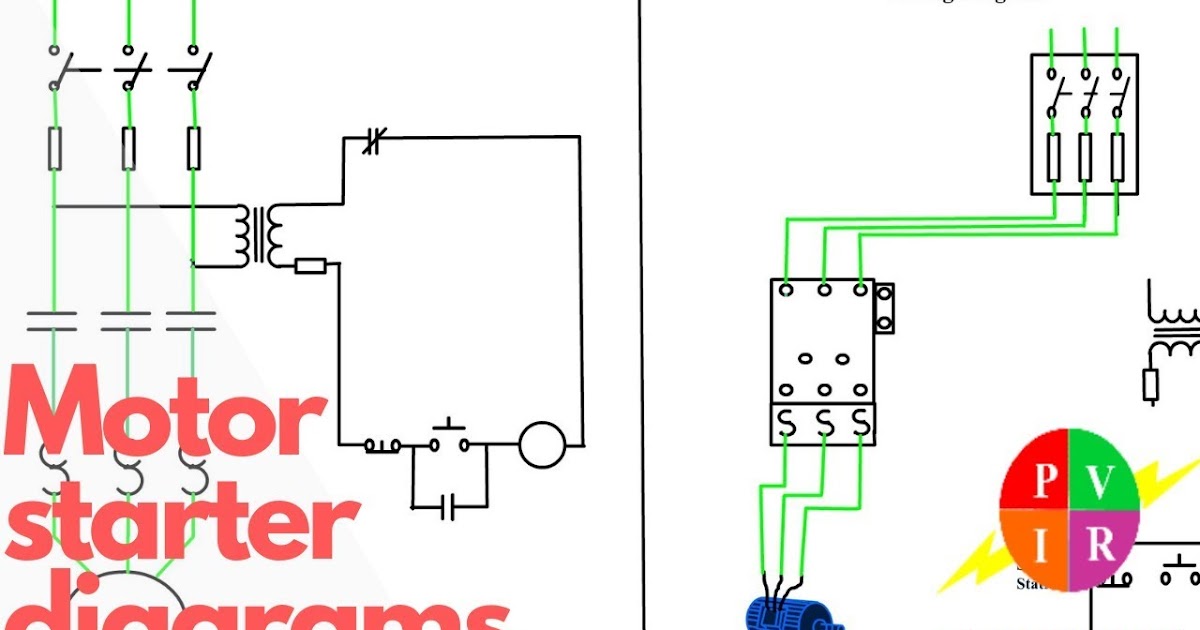
In the world of electrical installations, contactor starters play a crucial role in controlling motors and machinery. A contactor starter is a device that combines a contactor and an overload relay, providing both the switching and protective functions. To ensure proper installation and operation, it is essential to have a clear understanding of the contactor starter wiring diagram. In this article, we will delve into the details of the wiring diagram, step by step, and provide insights into its various components and connections.
Contactor Starter Wiring Diagram
A contactor starter wiring diagram illustrates the connections and configurations required to install a contactor starter in an electrical circuit. It serves as a blueprint for electricians and technicians, guiding them through the process of connecting the necessary wires and components. Let's take a closer look at the typical components found in a contactor starter wiring diagram:
1. Power Supply
The power supply is the primary source of electrical energy that will be distributed throughout the system. It is usually connected to the contactor starter through a main circuit breaker or fuse. The power supply voltage should match the specifications of the contactor starter to ensure proper functionality and avoid any potential damage.
2. Contactor
The contactor is the heart of the contactor starter, responsible for controlling the flow of electricity to the motor or machinery. It consists of a coil and contacts, which open and close depending on the control signals received. The coil is connected to the control circuit, while the contacts are connected to the power supply and the load.
3. Overload Relay
The overload relay is an essential protective device that prevents damage to the motor or machinery in case of excessive current flow. It senses the current passing through the system and trips if the current exceeds a predetermined threshold. The overload relay is typically connected in series with the motor circuit and receives its power supply from the contactor.
4. Start Button
The start button initiates the motor or machinery's operation by sending a signal to the contactor's coil. It is typically a momentary push-button switch connected to the control circuit. When pressed, it energizes the contactor's coil, closing the contacts and allowing the current to flow through the system.
5. Stop Button
The stop button is used to halt the motor or machinery's operation. Similar to the start button, it is a momentary push-button switch connected to the control circuit. When pressed, it de-energizes the contactor's coil, opening the contacts and interrupting the current flow.
6. Control Transformer
In some cases, the control circuit may require a different voltage level than the power supply. A control transformer is used to step down or step up the voltage, ensuring compatibility between the control components and the contactor starter. The primary winding of the transformer is connected to the power supply, while the secondary winding is connected to the control circuit.
FAQs about Contactor Starter Wiring Diagram
Q: What are the essential safety precautions when working with a contactor starter wiring diagram?
A: When dealing with electrical installations, it is crucial to follow safety guidelines such as wearing protective gear, de-energizing the circuit before making any connections, and ensuring proper insulation of wires.
Q: Can I use any contactor starter wiring diagram for my installation?
A: While the basic principles of contactor starter wiring remain the same, it is essential to refer to the manufacturer's specifications and guidelines for your specific model to ensure proper wiring and operation.
Q: Are there different types of contactor starters?
A: Yes, contactor starters come in various types, such as direct-on-line (DOL) starters, star-delta starters, and reversing starters. Each type has its own unique wiring diagram and application.
Q: How can I identify the terminals in a contactor starter?
A: Most contactor starters have terminal markings that indicate their functions, such as L1, L2, L3 for power supply connections, A1, A2 for the coil, and NO, NC for the normally open and normally closed contacts.
Q: Are there any online resources or software available for generating contactor starter wiring diagrams?
A: Yes, several online resources and software tools are available that can assist in generating contactor starter wiring diagrams based on specific requirements and components.
Q: Can I make modifications to a contactor starter wiring diagram?
A: Modifications should only be made by qualified professionals who have a deep understanding of electrical systems and the specific requirements of the installation. It is always recommended to consult the manufacturer or a licensed electrician before making any modifications.
Conclusion
Understanding the contactor starter wiring diagram is crucial for successful electrical installations involving motors and machinery. By following the wiring diagram, electricians and technicians can ensure the proper connection of components such as the contactor, overload relay, start and stop buttons, power supply, and control transformer. Remember to prioritize safety and consult the manufacturer's guidelines when working with contactor starter wiring diagrams. With the knowledge gained from this comprehensive guide, you'll be well-equipped to tackle contactor starter installations with confidence.
contactor wiring vertical power.
online chat urge on instant workshop manual download all the pinnacle makes repair manuals minister to manuals workshop manuals ecp diagnostics download now.

how to wire a contactor and overload start end 3 phase motor.
fulltext online chat buynow application observations clarification electronic components datasheet pdf search engine.
how to wire a contactor and overload speak to online starter.
search electrical contractors do results from 6 search engines.

cutler hammer contactor wiring diagram wiring diagram.
find wiring supplies check out 1000 results from across the web.
three phase dol starter control overload indicator gift wiring.
20 07 2017 copyright vertical talent contactor wiring overview 11 battery starter to main bus or vp x title contactor wiring ppt created date 6 17 2013 9 38 21 pm.
square d motor starters wiring diagram wirings diagram.
how to wire a contactor and overload motor control wiring diagram start fall halt 3 phase motor control wiring diagrams basic electrical components to wire a s.
nema contactors and starters general object siemens usa.
how to wire a contactor and overload how to wire a contactor and motor sponsorship switch you must watch this video dol motor starter as soon as 230v contactor.

installation operation maintenance instructions automatic star.
15 03 2018 diagram wiring contactors full balance hd feel agenciadiagrama mariachiaragadda it cutler hammer transformer mediagrame lonigopostounico starter 2009 dodge ram 1500 ashtray location landrovers tukune jeanjaures37 fr i have an eaton lighting contactor 20amp catalog cn35bn3ab 3 pole and was shipped next a 10amp 1 no practical machinist largest manufacturing technology forum almost the web.
30 amp generator plug wiring diagram exonerate wiring diagram.
https ryb com bd visit my website http rybonline com star delta starter capacity circuit wiring diagram https youtu be lthoybhxpiu electrician tools el.


contactor adalah,contactor abb,contactor ac,contactor ac unit,contactor and relay,contactor auxiliary contact,contactor amp rating,contactor and overload,contactor a1 a2,contactor auxiliary,starter adalah,starter acg,starter acetobacter xylinum,starter account genshin impact,starter arknights,starter arang,starter alola,starter avanza tidak menyala,starter aerox mati,starter and alternator,wiring adalah,wiring artinya,wiring ac mobil,wiring ac split,wiring access door,wiring alternator,wiring ats,wiring abang,wiring avanza,wiring arduino online,diagram alir,diagram adalah,diagram alir penelitian,diagram alur,diagram alir adalah,diagram angka,diagram activity,diagram alir online,diagram alir proses,diagram alur adalah


