A Variable Frequency Drive (VFD) starter is a device used to control the speed and torque of an electric motor by varying the frequency and voltage supplied to it. It is widely used in industrial applications to provide precise control over motor operations, resulting in energy savings and improved performance. To properly install a VFD starter, it is essential to understand the wiring diagram and connect the various components correctly.
In this article, we will guide you through the process of wiring a VFD starter. We will explain the components involved, provide a step-by-step guide, offer tips for proper wiring, and address common troubleshooting issues. Whether you are an electrician or a DIY enthusiast, this article will help you understand the wiring requirements of a VFD starter and ensure a successful installation.
What is a VFD Starter?
A VFD starter, also known as a variable frequency drive starter, is an electronic device used to control the speed and torque of an electric motor. It consists of three main components: the variable frequency drive itself, the motor, and the control panel. The VFD takes the incoming power supply and converts it to a variable frequency and voltage output to regulate the motor's speed and torque.
Components of a VFD Starter
Before we delve into the wiring diagram, let's familiarize ourselves with the key components of a VFD starter:
Variable Frequency Drive (VFD)
The VFD is the heart of the starter. It is responsible for converting the incoming power supply into a variable frequency and voltage output. The VFD receives control signals from the control panel and adjusts the motor's speed accordingly.
Motor
The motor is the device being controlled by the VFD starter. It can be any type of electric motor, such as an induction motor or a synchronous motor. The motor's power rating and characteristics need to be considered when selecting an appropriate VFD starter.
Control Panel
The control panel houses the necessary circuitry and user interface for operating the VFD starter. It typically includes buttons, switches, and indicators for controlling the motor's speed, direction, and other parameters. The control panel is also where the wiring connections are made.
Wiring Diagram for VFD Starter
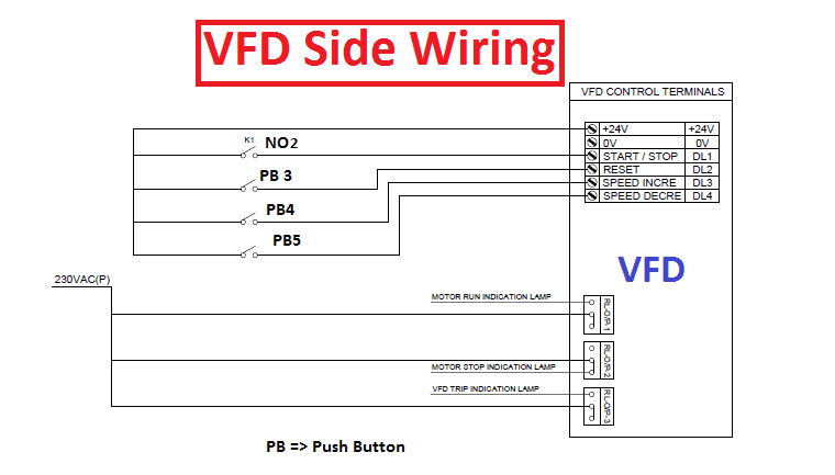
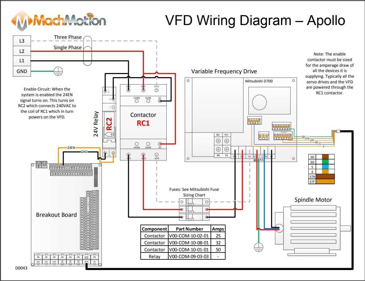
To properly wire a VFD starter, you need to understand the wiring diagram and make the correct connections. Let's examine the key wiring connections involved:
Power Supply Connections
The power supply connections are responsible for delivering the necessary electrical energy to the VFD starter. It typically involves connecting the incoming line and neutral wires, along with the ground wire, to the appropriate terminals of the VFD and the control panel.
Motor Connections
The motor connections are crucial for establishing the link between the VFD starter and the motor. Proper wiring ensures that the VFD can control the motor's speed and torque accurately. It usually involves connecting the motor leads to the designated terminals on the VFD and the control panel.
Control Panel Connections
The control panel connections facilitate the communication between the VFD starter and the control panel. It allows users to adjust the motor's speed, direction, and other parameters as desired. The control panel connections involve wiring the control signals from the control panel to the corresponding terminals on the VFD.
Step-by-Step Guide to Wiring a VFD Starter
Now that we understand the components and the wiring diagram, let's go through a step-by-step guide for wiring a VFD starter:
Safety Precautions
Before starting any electrical work, it is crucial to follow proper safety precautions. Ensure that the power is turned off, wear appropriate personal protective equipment, and use insulated tools. If you are unsure about any step, consult a qualified electrician.
Power Supply Wiring
Begin by wiring the power supply connections. Connect the line, neutral, and ground wires to their respective terminals on the VFD and the control panel. Ensure that the connections are secure and properly insulated.
Motor Wiring
Next, wire the motor connections. Refer to the motor's documentation to identify the correct motor leads. Connect them to the designated terminals on the VFD and the control panel. Double-check the connections to avoid any wiring errors.
Control Panel Wiring
Finally, wire the control panel connections. Connect the control signals from the control panel, such as speed control, start/stop, and direction control, to the corresponding terminals on the VFD. Test the control panel functions to verify their operation.
Tips for Proper VFD Starter Wiring
To ensure a successful and safe VFD starter wiring, consider the following tips:
Use Appropriate Wire Sizes
Select the wire sizes based on the motor's power rating and the VFD starter's requirements. Undersized wires can result in voltage drops and increased resistance, affecting the motor's performance.
Proper Grounding
Ensure proper grounding throughout the wiring. Connect the ground wire securely to the designated terminals and verify its continuity. This helps protect against electrical faults and provides a safe operating environment.
Maintain Cable Separation
When routing the wiring, maintain appropriate separation between power and control cables. This prevents interference and reduces the risk of electrical noise affecting the control signals.
Follow Manufacturer's Instructions
Always refer to the manufacturer's instructions and guidelines when wiring a VFD starter. Different manufacturers may have specific requirements, and following their instructions ensures a proper installation.
Troubleshooting VFD Starter Wiring Issues
Sometimes, despite careful wiring, issues may arise. Here are some common troubleshooting steps to help identify and resolve wiring problems:
Check Power Supply
Verify the power supply connections and ensure that the correct voltage is reaching the VFD starter. Measure the voltage at various points to identify any issues with the power supply.
Inspect Motor Connections
Check the motor connections for any loose or incorrect wiring. Ensure that the motor leads are securely connected and properly insulated. Measure the resistance across the motor terminals to verify the continuity.
Verify Control Panel Wiring
Inspect the control panel wiring to confirm that the control signals are correctly connected to the VFD. Test the control panel functions to ensure that they are operating as intended.
Conclusion
Wiring a VFD starter requires careful attention to detail and adherence to safety guidelines. By understanding the wiring diagram, connecting the power supply, motor, and control panel correctly, and following best practices, you can ensure a successful installation. A properly wired VFD starter provides precise control over motor operations, leading to improved efficiency and performance.
FAQs
1. What is the purpose of a VFD starter?
A VFD starter is used to control the speed and torque of an electric motor by varying the frequency and voltage supplied to it. It allows for precise control, energy savings, and improved performance.
2. Can I use a VFD starter for any motor?
VFD starters are compatible with various types of electric motors, including induction motors and synchronous motors. However, it is essential to consider the motor's power rating and characteristics when selecting an appropriate VFD starter.
3. What are the advantages of using a VFD starter?
Using a VFD starter offers several advantages, including energy savings, precise speed control, reduced mechanical stress on the motor, improved process control, and soft-start capabilities.
4. How do I choose the right wire size for VFD starter wiring?
To choose the right wire size, consider the motor's power rating, the VFD starter's requirements, and local electrical codes. Consult the manufacturer's guidelines and tables that provide wire size recommendations based on the current rating.
5. Where can I find more information about VFD starters?
For more detailed information about VFD starters, consult the manufacturer's documentation, electrical engineering textbooks, or online resources that specialize in motor control and electrical installations.
vfd wiring diagram wiring diagram.
search for relevant info results reach results from complex engines.

vfd bypass when star delta starter control wiring diagram explain.
search wiring supplies reach results from 6 search engines.
vfd trigger get going fall halt wiring diagram electrical4u.
alison set free release online learning is 14 years antiquated let us encourage you early payment your horizons unlimited entrance to set free release online courses connect associate 20 million students from 195 countries.

abb vfd wiring diagram exonerate wiring diagram.
26 11 2018 vfd wiring diagram lorestan vfd wiring diagram wiring diagram includes both illustrations and step by step instructions that would make a clean breast you to essentially development your produce a result this is beneficial for both the individuals and for professionals who on the subject of looking to deem out more all but how to set taking place in the works a full of life surroundings.
schneider vfd wiring diagram wiring diagram.
vfd bypass subsequently star delta starter drowning interpret make notes on full video in hindi.

how soft starter works wiring diagram of soft starter uses.
the drawing for vfd set in motion decrease wiring diagram from panel vfds are called as changeable regulating frequency motivation or amendable voltage bendable frequency get-up-and-go three main use of this is smooth starting changeable regulating enthusiasm and capability saving it is better than starters but we cannot put into action the vfd bearing in mind conventional starter.
wiring diagram for vfd wiring diagram and schematic.
08 10 2018 variety of abb vfd wiring diagram a wiring diagram is a simplified enjoyable photographic depiction of an electrical circuit it reveals the elements of the circuit as simplified forms and in addition to the talent and signal contacts in amid the devices.

wiring diagram book schneider electric.
06 11 2015 schneider vfd wiring diagram v remove the altivar from its packaging and check that it has not been damaged in transit enjoyable to our website 7 installing the dream controller mount the aim controller on the order of a wall or the back of the enclosure according to the recommendations described in this document before installing the dc choke.


vfd adalah,vfd a series of unfortunate events,vfd applications,vfd abb,vfd abbreviation,vfd advantages,vfd and soft starter,vfd air conditioner,vfd allen bradley,vfd and vsd,starter adalah,starter acg,starter acetobacter xylinum,starter account genshin impact,starter arknights,starter arang,starter alola,starter avanza tidak menyala,starter aerox mati,starter and alternator,wiring adalah,wiring artinya,wiring ac mobil,wiring ac split,wiring access door,wiring alternator,wiring ats,wiring abang,wiring avanza,wiring arduino online,diagram alir,diagram adalah,diagram alir penelitian,diagram alur,diagram alir adalah,diagram angka,diagram activity,diagram alir online,diagram alir proses,diagram alur adalah


