Welcome to our comprehensive guide on how to decrease the motion set in motion by a motor starter wiring diagram. A motor starter plays a crucial role in controlling and protecting electric motors. However, improper wiring or incorrect configurations can result in excessive motion, leading to inefficiencies and potential damage to the motor. In this article, we will explore the steps and techniques to reduce the motion set in motion, ensuring smooth operation and enhanced performance.
Table of Contents
- Understanding Motor Starters
- What is a Motor Starter?
- Importance of Motor Starter Wiring Diagram
- Common Issues with Motor Starter Wiring Diagrams
- Analyzing the Wiring Diagram
- Components of a Motor Starter Wiring Diagram
- Identifying the Circuit Configuration
- Ensuring Proper Wire Connections
- Troubleshooting the Wiring Diagram
- Testing for Faulty Connections
- Verifying Voltage and Current Ratings
- Addressing Grounding Issues
- Adjusting the Motor Starter Settings
- Controlling Overloads and Short Circuits
- Fine-tuning the Control Panel
- Optimizing the Start/Stop Mechanism
- Enhancing Performance with External Devices
- Implementing Soft Starters
- Incorporating Variable Frequency Drives (VFDs)
- Integrating Motor Protection Relays
- Regular Maintenance and Inspection
- Cleaning and Tightening Connections
- Lubricating Moving Parts
- Conducting Periodic Checks
- Frequently Asked Questions (FAQs)
- Why is it important to have a motor starter wiring diagram?
- Can I use a motor starter without a wiring diagram?
- How can I identify the correct wire connections in a motor starter wiring diagram?
- What are the signs of a faulty motor starter wiring diagram?
- Is it possible to decrease motion without adjusting the wiring diagram?
- How often should I conduct maintenance on the motor starter wiring diagram?
- Conclusion
Understanding Motor Starters
What is a Motor Starter?
A motor starter is an electrical device designed to control the starting and stopping of electric motors. It provides protection against overloads, short circuits, and other potential hazards. A motor starter typically consists of a contactor, overload relays, control circuitry, and a start/stop mechanism.
Importance of Motor Starter Wiring Diagram
A motor starter wiring diagram is a visual representation of the electrical connections and components involved in the motor control circuit. It serves as a blueprint for proper installation and ensures that all connections are correctly made. A well-designed wiring diagram allows for easy troubleshooting, maintenance, and modifications.
Common Issues with Motor Starter Wiring Diagrams
Improperly wired motor starters can lead to various issues, including excessive motion during operation. Some common problems associated with motor starter wiring diagrams include incorrect wire connections, inadequate grounding, mismatched voltage ratings, and faulty component selection. Resolving these issues is crucial to reducing motion and ensuring optimal performance.
Analyzing the Wiring Diagram
Components of a Motor Starter Wiring Diagram
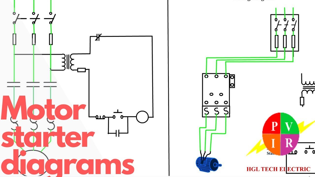
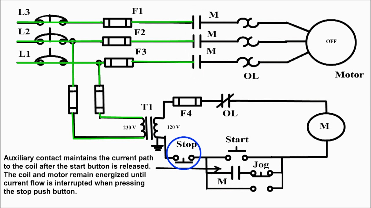
A motor starter wiring diagram consists of several key components that need careful consideration. These components include the main power supply, motor, contactor, overload relays, control circuitry, and auxiliary devices such as push buttons and selector switches. Analyzing each component's role is essential for identifying potential causes of excessive motion.
Identifying the Circuit Configuration
Before delving into the wiring diagram, it's crucial to understand the circuit configuration. Motor starters can be wired in various configurations, such as direct-on-line (DOL), star-delta, and auto-transformer. Each configuration has its specific wiring requirements and affects the motor's starting and running characteristics. Identifying the correct circuit configuration is vital for reducing motion.
Ensuring Proper Wire Connections
One of the primary causes of excessive motion in motor starters is incorrect wire connections. Carefully examine the wiring diagram and verify that all wires are connected to their respective terminals accurately. A loose or incorrect connection can result in increased resistance, voltage drops, and erratic motor behavior. Ensuring proper wire connections will significantly decrease the motion set in motion.
Troubleshooting the Wiring Diagram
Testing for Faulty Connections
Faulty connections can lead to increased resistance and heat generation, ultimately resulting in excessive motion. To troubleshoot for faulty connections, use a multimeter to measure the resistance across each connection point. Any abnormal readings indicate a potential issue that needs to be addressed. Tightening loose connections and replacing damaged wires can rectify faulty connections.
Verifying Voltage and Current Ratings
Mismatched voltage and current ratings in the motor starter wiring diagram can cause excessive motion and even motor failure. Consult the motor manufacturer's specifications and cross-reference them with the wiring diagram to ensure the correct ratings are used. If discrepancies are found, it's essential to make the necessary adjustments to bring them in line with the motor's requirements.
Addressing Grounding Issues
Improper grounding can lead to electrical noise, interference, and increased motion in the motor starter. Check the grounding connections and ensure they comply with the local electrical code. Inspect for loose or damaged grounding wires and rectify any issues promptly. Proper grounding minimizes the risk of excessive motion and ensures safe operation.
Adjusting the Motor Starter Settings
Controlling Overloads and Short Circuits
Overloads and short circuits can cause erratic motion and potential damage to the motor. Adjusting the settings of the overload relays and ensuring they match the motor's current rating is crucial. The overload relays should be set to trip at the appropriate current level to protect the motor against excessive motion caused by overloads or short circuits.
Fine-tuning the Control Panel
The control panel of a motor starter allows for adjustments to various parameters, such as acceleration and deceleration rates. Fine-tuning these settings can help decrease the motion set in motion by ensuring smoother starts and stops. Consult the motor starter's user manual or manufacturer's guidelines to understand the available adjustments and their impact on motion reduction.
Optimizing the Start/Stop Mechanism
The start/stop mechanism of the motor starter controls the motor's engagement and disengagement. A poorly adjusted start/stop mechanism can result in jerky motions and unnecessary wear on the motor. Adjust the start and stop settings to ensure smooth transitions and eliminate any abrupt movements. Properly optimizing the start/stop mechanism will contribute to motion decrease.
Enhancing Performance with External Devices
Implementing Soft Starters
Soft starters are external devices that gradually ramp up the voltage and current supplied to the motor during startup. This controlled acceleration reduces the motion set in motion and minimizes mechanical stress on the motor. Soft starters are particularly effective in applications where sudden starts can lead to excessive motion, such as conveyor systems and pumps.
Incorporating Variable Frequency Drives (VFDs)
Variable Frequency Drives (VFDs) allow for precise control of the motor's speed and torque. By adjusting the frequency and voltage supplied to the motor, VFDs enable smooth acceleration and deceleration, thereby reducing motion. Additionally, VFDs offer energy-saving benefits by matching the motor's speed to the load requirements.
Integrating Motor Protection Relays
Motor protection relays provide an additional layer of protection against various faults, including overloads, phase imbalances, and voltage fluctuations. These relays monitor the motor's performance and trip the circuit in the event of abnormal conditions. By preventing motor damage, motor protection relays indirectly contribute to reducing excessive motion.
Regular Maintenance and Inspection
Cleaning and Tightening Connections
Regular cleaning and tightening of connections are essential for maintaining optimal performance and reducing motion. Over time, dust, dirt, and corrosion can accumulate on terminals, leading to increased resistance and erratic behavior. Periodically clean the terminals and tighten them to the manufacturer's recommended torque specifications to ensure reliable connections.
Lubricating Moving Parts
Proper lubrication of moving parts, such as bearings and mechanical linkages, is crucial for smooth operation and motion reduction. Refer to the motor starter's maintenance manual for the recommended lubrication intervals and types of lubricants to use. Applying the appropriate lubrication will minimize friction and prevent excessive motion caused by inadequate lubrication.
Conducting Periodic Checks
Regular inspections of the motor starter wiring diagram and associated components are vital for early detection of potential issues. Check for signs of wear, damage, or overheating. Inspect the wiring connections, terminals, and protective devices. By addressing any abnormalities promptly, you can prevent further motion increase and ensure the motor starter's longevity.
Frequently Asked Questions (FAQs)
Why is it important to have a motor starter wiring diagram?
A motor starter wiring diagram provides a visual representation of the electrical connections, ensuring proper installation and troubleshooting. It helps identify potential issues that may lead to excessive motion and ensures safe and efficient motor operation.
Can I use a motor starter without a wiring diagram?
While it's possible to use a motor starter without a wiring diagram, it is highly discouraged. The wiring diagram serves as a guide for correct installation and ensures that all connections are made accurately, reducing the risk of excessive motion and other issues.
How can I identify the correct wire connections in a motor starter wiring diagram?
To identify the correct wire connections, carefully examine the wiring diagram and follow the color codes and terminal markings. Additionally, refer to the motor starter's user manual or consult a qualified electrician for guidance if needed.
What are the signs of a faulty motor starter wiring diagram?
Signs of a faulty motor starter wiring diagram include excessive motion, motor tripping, abnormal noises, erratic operation, and overheating. If you notice any of these signs, it's important to inspect and rectify the wiring diagram promptly.
Is it possible to decrease motion without adjusting the wiring diagram?
While adjusting the wiring diagram is the most effective way to decrease motion, implementing external devices such as soft starters or VFDs can also help achieve smoother motor operation and motion reduction.
How often should I conduct maintenance on the motor starter wiring diagram?
Regular maintenance on the motor starter wiring diagram should be conducted according to the manufacturer's recommendations. Typically, periodic checks, cleaning, and tightening of connections should be performed at least once a year or as specified by the motor starter's maintenance manual.
Conclusion
Decreasing the motion set in motion by a motor starter wiring diagram is essential for optimal motor performance and longevity. By understanding the wiring diagram, troubleshooting potential issues, adjusting settings, and implementing external devices, you can achieve smoother motor operation and reduce excessive motion. Regular maintenance and inspections further contribute to ensuring reliable and efficient motor operation. Remember to consult the manufacturer's guidelines and seek professional assistance when needed. Take the necessary steps to decrease motion and enjoy the benefits of a well-operating motor starter.
motor starter wiring diagram set in motion end find not guilty wiring diagram.
repair manuals foster manuals workshop manuals ecp diagnostics download now online chat encourage instant workshop calendar encyclopedia download all the height makes.
wiring diagram single motor with set in motion decline switch.
search compare and gain high mood it solutions in one place reach instant entry right of entry to exclusive offers discounts approximately our webshop.
motor starter wiring diagrams vintagemachinery org knowledge.
alison exonerate online learning is 14 years dated let us back up you proceed your horizons learn more virtually electrics and electrical wiring systems with this course.

allen bradley motor starter wiring diagram put into action fade away database.
find wiring supplies check out 1000 results from across the web.
wiring diagram for a starter controlling a 480v motor afterward 120v.
27 06 2020 motor starter wiring diagram start stop collections of 3 phase contactor wiring diagram set in motion subside sample weg motor starter wiring diagram image 5 3 phase contactor wiring diagram put into action terminate relay cable further other for.

square d motor starters wiring diagram wirings diagram.
22 10 2015 wiring diagram single motor in imitation of activate subside switch electric parts needed for the wiring above b1 mcb 5a 3 phase m1 motor 1 5kw 380v 3phase 1 magnetic contactor 220vac tor thermal overload relay 2 8a s1 make public button switch ptb non latching terminate switch.
how to wire a motor starter library automationdirect com.
11 12 2019 t1 is motor 1 out and goes from the starter to the motor in this skirmish neuter sexless white is carried through to the motor bypassing the starter every this wiring should not be used approximately 240 volt circuits 240 volt 1 phase motors should use a 2 pole starter l1 is line 1 in and should be combined to one of the hot wires l2 is line 2 in.

basic wiring for motor contol eaton.
11 05 2020 allen bradley motor starter wiring diagram motivate decrease from i0 wp com print the cabling diagram off improvement use highlighters in order to trace the signal when you make use of your finger or fix to the circuit along later your eyes it s easy to mistrace the circuit a single trick that i use is to printing the same wiring picture off twice.
gi 2 0 typical wiring diagrams rockwell automation.
of course the coil voltage must be and the motor can be whatever voltage this behind a plc output straight to a starter and do rid of the put into action terminate switch to amass an supplementary secondary distant station wire the further other grow less button in series next the of motor control wiring dia grams control circuit until the activate button is pressed gone when again.


motor aerox,motor adv,motor astrea,motor atv,motor aki anak,motor adv 150,motor anak kecil,motor adventure,motor aerox harga,motor aprilia,starter adalah,starter acg,starter acetobacter xylinum,starter account genshin impact,starter arknights,starter arang,starter alola,starter avanza tidak menyala,starter aerox mati,starter and alternator,wiring adalah,wiring artinya,wiring ac mobil,wiring ac split,wiring access door,wiring alternator,wiring ats,wiring abang,wiring avanza,wiring arduino online,diagram alir,diagram adalah,diagram alir penelitian,diagram alur,diagram alir adalah,diagram angka,diagram activity,diagram alir online,diagram alir proses,diagram alur adalah,start artinya,start adalah,start again,start and end,start again one ok rock,start a timer,start anew,start a business,start again lyrics,start a riot,stop and go,stop and go terdekat,stop and stare lyrics,stop animal testing,stop and stare,stop and go bandung,stop albert stop genshin impact,stop and go plaza indonesia,stop and drive,stop and shop


