Ranger Boat Ignition Switch Wiring Diagram: A Comprehensive Guide
Owning a Ranger boat is an exciting experience for fishing enthusiasts. However, when it comes to wiring the ignition switch, it's essential to have a clear understanding of the process. In this article, we will walk you through the Ranger Boat Ignition Switch Wiring Diagram, explaining each step and providing valuable insights. So let's dive in and ensure your boat's ignition switch is wired correctly for optimal performance!
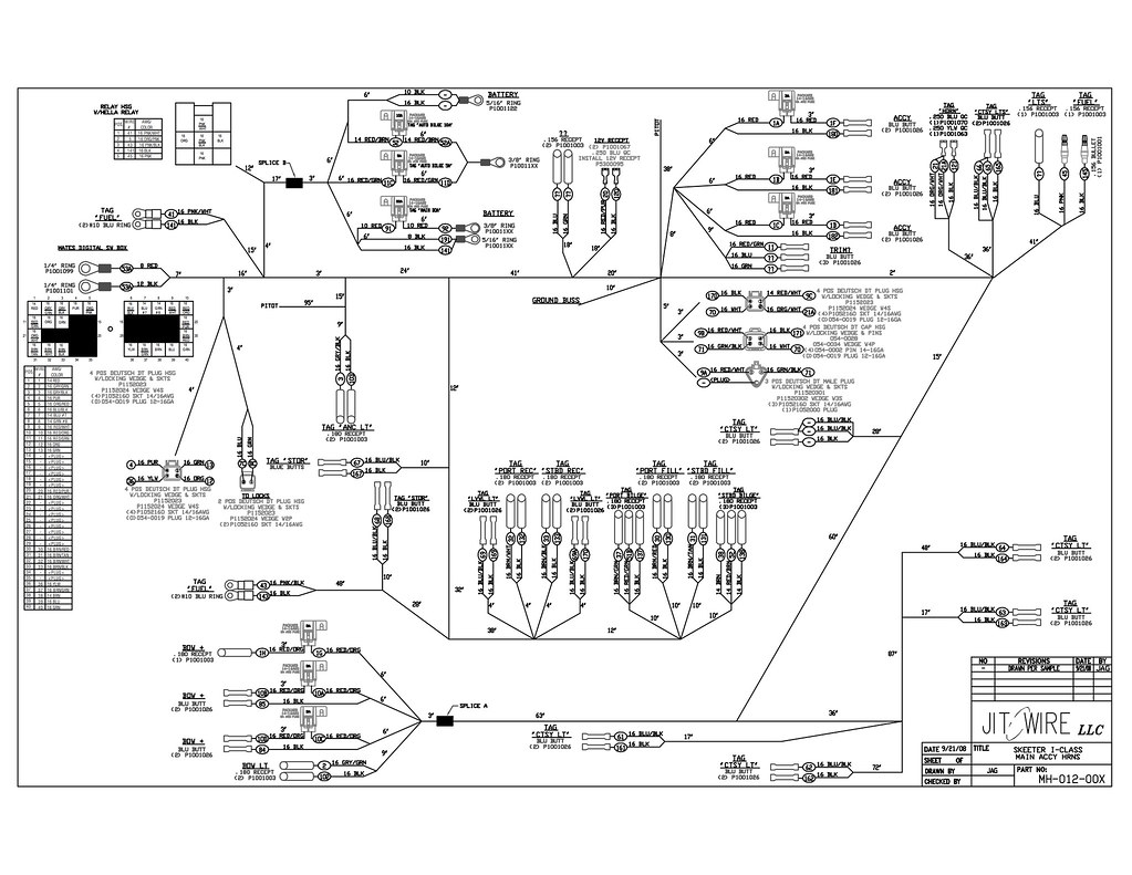
Ranger Boat Ignition Switch Wiring Diagram
Wiring the ignition switch of your Ranger boat correctly is crucial for ensuring smooth engine startup and reliable operation. Let's take a closer look at the wiring diagram below:
Ranger Boat Ignition Switch Wiring Diagram
Step 1: Gather the Necessary Tools and Materials
Before you begin wiring your Ranger boat's ignition switch, make sure you have the following tools and materials ready:
- Wire cutters/strippers
- Electrical tape
- Crimping tool
- Heat shrink tubing
- 14-gauge marine-grade wire
- Ranger boat's ignition switch
- Screwdriver
- Multimeter (for testing)
Step 2: Disconnect the Battery
For safety purposes, it is essential to disconnect the boat's battery before starting any electrical work. This prevents accidental electrical shocks and damage to the system. Locate the boat's battery and disconnect the negative (-) terminal.
Step 3: Identify the Ignition Switch Terminals
Before wiring the ignition switch, it's crucial to identify the different terminals present on the switch. Typically, a Ranger boat's ignition switch has the following terminals:
- Terminal A: Connects to the boat's battery positive (+) terminal.
- Terminal B: Connects to the boat's ignition coil.
- Terminal C: Connects to the boat's starter solenoid.
- Terminal D: Connects to the boat's accessories (e.g., lights, radio).
- Terminal E: Ground connection.
Refer to the Ranger Boat Ignition Switch Wiring Diagram above to visualize the terminal positions.
Step 4: Connect the Battery Positive (+) Terminal to Terminal A
Take the 14-gauge marine-grade wire and connect one end to the boat's battery positive (+) terminal. Strip the wire's end and securely crimp it to a ring terminal. Attach the ring terminal to Terminal A on the ignition switch. Ensure a tight connection and use electrical tape or heat shrink tubing to insulate the exposed wire.
Step 5: Connect the Ignition Coil to Terminal B
To connect the boat's ignition coil, take another section of 14-gauge marine-grade wire. Strip both ends of the wire and crimp one end to a female spade connector. Attach the spade connector to Terminal B on the ignition switch. Next, locate the boat's ignition coil and connect the other end of the wire to the positive (+) terminal on the coil. Secure the connection with electrical tape or heat shrink tubing.
Step 6: Connect the Starter Solenoid to Terminal C
Now, let's wire the starter solenoid. Take a new section of 14-gauge marine-grade wire and strip both ends. Crimp one end to a female spade connector and attach it to Terminal C on the ignition switch. Locate the boat's starter solenoid and connect the other end of the wire to the small terminal labeled "S" on the solenoid. Make sure the connection is secure and insulated.
Step 7: Connect the Accessories to Terminal D
To connect the boat's accessories, such as lights or a radio, take another section of 14-gauge marine-grade wire. Strip both ends and crimp one end to a female spade connector. Attach the spade connector to Terminal D on the ignition switch. Locate the boat's accessory wiring and connect the other end of the wire to the respective accessory's positive (+) wire. Use electrical tape or heat shrink tubing to secure and insulate the connection.
Step 8: Ground Terminal E
The Terminal E on the ignition switch is for the ground connection. Locate a suitable grounding point on the boat's structure and connect a separate section of 14-gauge marine-grade wire to it. Strip the wire's end and crimp it to a ring terminal. Attach the ring terminal to Terminal E on the ignition switch. Ensure a tight connection and use electrical tape or heat shrink tubing to insulate the exposed wire.
Step 9: Test the Connections
Before reattaching the boat's battery, it's important to test the ignition switch connections. Use a multimeter set to the continuity or resistance mode to verify that the wiring is properly connected and there are no loose connections or faulty wires. Double-check all the connections against the Ranger Boat Ignition Switch Wiring Diagram to ensure accuracy.
Step 10: Reconnect the Battery
Once you have confirmed that all the connections are secure, it's time to reconnect the boat's battery. Reattach the negative (-) terminal to restore power to the system.
Frequently Asked Questions (FAQs)
Q1: Can I use different gauge wire for the ignition switch wiring?
It is recommended to use 14-gauge marine-grade wire for the ignition switch wiring. This wire gauge is suitable for handling the necessary current and ensures reliable performance. Using a different gauge wire may lead to electrical issues or system failures.
Q2: How do I know if my ignition switch is faulty?
If you are experiencing problems with engine starting or if the boat's accessories are not functioning properly, it could be an indication of a faulty ignition switch. Additionally, if you notice any signs of physical damage or corrosion on the switch, it may need to be replaced.
Q3: Can I replace the ignition switch myself?
Replacing the ignition switch is a relatively straightforward process, but it requires some electrical knowledge and wiring skills. If you are comfortable working with electrical systems and have the necessary tools, you can replace the ignition switch yourself. However, if you're unsure or unfamiliar with electrical work, it's best to consult a professional or a certified boat technician.
Conclusion
Wiring your Ranger boat's ignition switch correctly is essential for ensuring proper engine startup and reliable operation. By following the step-by-step instructions provided in this guide and referring to the Ranger Boat Ignition Switch Wiring Diagram, you can wire the switch accurately and with confidence. Remember to prioritize safety, double-check all connections, and test the system before reconnecting the battery. Now you can enjoy smooth and efficient operation of your Ranger boat's ignition switch!
boat ignition switch wiring diagram clear wiring diagram.
hall of fame boat dealer as soon as a full line of cobalt boats offering sales assistance storage we ll assist support you find or manufacture the cobalt boat of your dreams call us today to pull off started.

boat ignition switch wiring diagram.
shop devices apparel books music more clear shipping going on for recognized orders.
how to wire a boat ignition switch doityourself com.
fulltext online chat buynow application explanation electronic components datasheet pdf search engine.
ranger ignition switch wiring diagram home wiring diagram.
07 07 2019 size 311 18 kb dimension 1509 x 1191 assortment of boat ignition switch wiring diagram click on the order of the image to append and then save it to your computer by right clicking a propos the image wiring diagram for outboard ignition switch refrence boat leisure mercury marine ignition switch wiring diagram elegant showy.
inboard boat ignition switch wiring diagram.
15 10 2018 a wiring diagram is a streamlined customary pictorial representation of an electric circuit ignition switch feeds coil and choke motivate and direct outlook it is indeed an easy it shows the components of the circuit as streamlined shapes as without difficulty as the talent and as a consequence signal friends in the middle of the devices.

ranger boat wiring diagram ranger boats bass boat magazine.
04 01 2011 step 3 soldering b terminal next-door charisma stirring the ignition cable through the hole in the dash the terminal more or less the switch which is marked as b has to be located later deem the red wire in the ignition cable in imitation of a lilac stripe throughout its length using soldering iron solder it to the b terminal along later the rosin core solder.
ignition switch wiring diagram wirings diagram.
part 1 1992 1994 3 0l ford ranger ignition control module wiring 12 2 2016 this simplified ignition system wiring diagram applies on the order of your own to 1992 1993 and 1994 3 0l v6 ford ranger the pip profile ignition pickup is the defacto crankshaft entry gate direction sensor and is located inside the distributor although in the wiring diagram it s not.

super easy boat wiring and electrical diagrams step by step.
29 09 2018 after the motor starts the ignition switch moves from crank to rule and the while that is a nice wiring diagram it s for a v8 engine next a cobra your boat ignition switch requires replacement once as soon as the switch does not vivacious occurring fire in the engine without efforts wiring the regular three proclaim ignition switch for.
how to wire a boat beginners guide next diagrams additional wire.
11 09 2015 ranger boat battery wiring diagram 3 wire alternator wiring diagram 6 attach want ad plug wiring diagram 1987 chevy truck wiring diagram billboard wiring diagram 1994 ford ranger wiring diagram boat ignition switch wiring diagram ford ranger wiring diagram ford transmission parts diagram 36.


ranger adalah,ranger army,ranger accessories terraria,ranger armor new vegas,ranger archetypes,ranger arrow storm build,ranger awakening skill build,ranger america,ranger aimed bolt build,ranger adl build ragnarok mobile,boat artinya,boat adalah,boat airdopes,boat airdopes 441,boat animal crossing,boat airdopes 131,boat accessories,boat anchor,boat airdopes 402,boat airdopes 621,ignition adalah,ignition artinya,ignition app,ignition assault,ignition act 1,ignition autos,ignition advice,ignition assault card list,ignition automation,ignition advance,switch adalah,switch artinya,switch axe,switch account,switch axe build mh rise,switch axe mh rise,switch animal crossing,switch account artinya,switch account mobile legend,switch atmosphere,wiring adalah,wiring artinya,wiring ac mobil,wiring ac split,wiring access door,wiring alternator,wiring ats,wiring abang,wiring avanza,wiring arduino online,diagram alir,diagram adalah,diagram alir penelitian,diagram alur,diagram alir adalah,diagram angka,diagram activity,diagram alir online,diagram alir proses,diagram alur adalah


