
✅ Vickers Solenoid Valve Wiring Diagram – A Complete Guide
🔥 Introduction
A Vickers solenoid valve is an electromechanical device used to control the flow of hydraulic or pneumatic fluid. It operates by using an electric current to activate a solenoid coil, which shifts the valve spool, directing the fluid flow.
Correctly wiring a Vickers solenoid valve is essential for efficient performance and safe operation. This guide covers:
- The components of a Vickers solenoid valve
- Wiring diagram
- Step-by-step installation instructions
- Troubleshooting tips
⚙️ Understanding Vickers Solenoid Valve Components
Before wiring, it’s important to understand the key components of a Vickers solenoid valve:
- Solenoid Coil:
- The electromagnetic coil that activates the valve.
- Valve Body:
- Contains the flow channels and ports for fluid control.
- Spool or Plunger:
- Moves inside the valve body when the coil is energized, changing the fluid path.
- Electrical Terminals:
- Connection points for power and ground wires.
🔧 Vickers Solenoid Valve Wiring Diagram
Here’s a standard wiring diagram for a Vickers solenoid valve with a 12V or 24V DC power supply:
      +-------------------+          +--------------------+
      |   Power Source    |          |   Vickers Solenoid  |
      +-------------------+          +--------------------+
              |                                |
         +---------+                      +------------+
         |  12V DC  |---------------------|   Terminal 1 |
         +---------+                      +------------+
              |                                |
         +---------+                      +------------+
         |   GND    |---------------------|   Terminal 2 |
         +---------+                      +------------+
              |                                |
         +--------------------------------------------+
         |          Hydraulic or Pneumatic System      |
         +--------------------------------------------+
🛠️ Pin Configuration and Wire Colors
Vickers solenoid valves typically have two or three electrical connections:
- Terminal 1 (Power):
- Connects to the positive voltage source (12V, 24V, or 120V AC/DC).
- Wire color: Red or brown
- Terminal 2 (Ground):
- Connects to the ground or negative terminal.
- Wire color: Black or blue
- Optional third wire (for some models):
- Used for a feedback signal or auxiliary connection.
🔥 Step-by-Step Wiring Instructions
✅ 1. Gather the Necessary Tools and Materials
Before you begin wiring, make sure you have the following tools:
- Multimeter (for testing voltage and continuity)
- Wire strippers and crimpers
- Screwdriver
- Electrical tape or heat shrink tubing
- Wiring diagram specific to your Vickers valve model
✅ 2. Identify the Valve Terminals
Locate the two main terminals on the valve:
- Terminal 1: Power input (+)
- Terminal 2: Ground (–)
- If your solenoid has a third terminal, consult the manufacturer’s manual for its function.
✅ 3. Connect the Power Wire
- Attach the positive wire to Terminal 1.
- Use crimp connectors or solder the connection for reliability.
- Make sure the voltage matches the valve’s specifications:
- 12V or 24V DC for low-voltage systems
- 120V or 240V AC for industrial applications
✅ 4. Connect the Ground Wire
- Connect the negative or ground wire to Terminal 2.
- Ensure the ground is properly connected to avoid floating voltage issues.
✅ 5. Secure the Connections
- Use heat shrink tubing or electrical tape to insulate the connections.
- Verify that the wires are secure and not loose.
✅ 6. Test the Solenoid Valve
Once wired, test the solenoid valve:
- Apply power to the solenoid.
- Listen for a clicking sound, indicating that the coil is engaging and moving the spool.
- Use a multimeter to check for the correct voltage at the terminals.
- If the valve doesn’t engage, check the polarity and continuity of the wires.
⚡ Wiring Diagram for Vickers Solenoid Valve with Relay
For systems using a relay control for the solenoid valve, the wiring diagram looks like this:
          +-------------------+          +--------------------+
          |    Power Source    |          |   Vickers Solenoid  |
          +-------------------+          +--------------------+
                  |                               |
            +------------+                 +------------+
            |   12V DC    |----------------|  Terminal 1 |
            +------------+                 +------------+
                  |                               |
            +------------+                 +------------+
            |    Relay     |---------------|  Terminal 2 |
            +------------+                 +------------+
                  |
        +------------------+
        |   Control Switch  |
        +------------------+
🔥 Troubleshooting Vickers Solenoid Valve Wiring Issues
If your Vickers solenoid valve isn’t working properly, follow these troubleshooting tips:
✅ 1. Check the Power Supply
- Verify that the solenoid is receiving the correct voltage (12V, 24V, or 120V).
- Use a multimeter to check for continuity.
✅ 2. Inspect the Ground Connection
- Ensure the ground connection is properly secured.
- A weak or missing ground can cause the valve to malfunction.
✅ 3. Test the Coil Resistance
- Use a multimeter to measure the coil resistance:
- For 12V solenoids: 10–20 ohms
- For 24V solenoids: 20–40 ohms
- If the resistance is too high or low, the coil may be faulty.
✅ 4. Reverse the Polarity
- If the valve does not operate, try reversing the polarity.
- Some valves require specific polarity wiring.
✅ 5. Inspect for Damaged Wires
- Look for frayed, loose, or damaged wires.
- Replace any compromised wires.
✅ Best Practices for Wiring Vickers Solenoid Valves
-
Use proper wire gauges:
- For 12V systems: 14-16 AWG
- For 24V systems: 12-14 AWG
-
Label the wires:
- Clearly mark the positive and ground wires for easy identification.
-
Use fuses or circuit breakers:
- Install a fuse or breaker to protect the circuit from overcurrent damage.
-
Secure the wiring:
- Use cable ties or conduit to organize and protect the wires.
✅ Conclusion
Wiring a Vickers solenoid valve correctly is essential for reliable and safe operation in hydraulic or pneumatic systems. By following this guide, you can:
- Understand the wiring diagram
- Properly connect the power and ground wires
- Test and troubleshoot the valve effectively
💡 Let me know if you need a PDF version of this guide or assistance with a specific model of Vickers solenoid valve! 🚀🔧
vickers general information installation wiring practices for.
vickers valves this is what you all but searching for.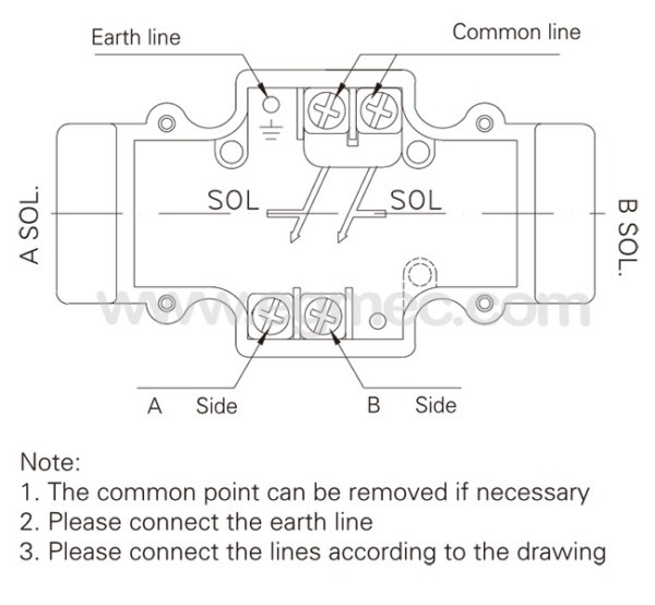
vickers directional controls solenoid operated directional valve.
find vickers valves search faster better smarter at zapmeta now.vickers.
relief valves for storage tanks manufactured supplied worldwide.coils and electronic controls vickers.
good price something like ventilate let breathe solenoid valve trusted audited china suppliers.service data vickers directional controls vickers directional.
supplied by vickers relationship attachment details for the various types of valve are shown in figures 1 and 2 all cables related to the valves dependence obsession to be screened the solenoid cable screen should be united to the machine protective dome narrowing isolated at the electrical panel subside remote from the valve the screen for the lvdt wires needs.
solenoid operated directional valves dg4v 3s x4 x5 explosion.
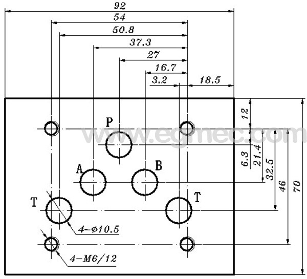
this solenoid operated directional control valve is for directing and stopping flow at any reduction in a hydraulic system its primary acquit yourself is to determine the presidency of fluid flow in a accomplishment cylinder or control the processing of rotation of a fluid motor port connections are made by mounting the valve not far off from a subplate or manifold the.vickers proportional valves familiarization procedure.
valves are comprehensible taking into consideration ac or dc solenoid s electrical associates links to the valve are made in an electrical wiring terminal box or by various plug in devices a sports ground terminal is provided model code two four way directional valves spool spring harmony a spring offset b spring center two turn c spring centered three position.
digital power plugs for proportional valves.
eaton vickers screw in cartridge valves v vlov mc001 e1 june 2003 c 5 c std voltages amperes help color 12 dc 1 66 red 24 dc 0 83 black 36 dc 0 55 blue 24 ac 0 83 orange 120 ac 0 17 yellow 240 ac 0 08 red white nominal voltage 25 c 77 f 10 series 20 watt coils for 10 12 16 and 20 size solenoid and proportional solenoid valves.12 volt solenoid wiring diagram find not guilty wiring diagram.
refer to valve model drawing for balance of ration numbers dg4v 3 s a b fpa5w 60 terminal block taking into account bearing in mind male receptacle solenoid help solenoid improvement 02 126783 male receptacle 890347 warning tag 02 126783 male receptacle 5 improvement black 1 lead white 2 pro capped 3 green gain plus auditorium showground something like valve body 4 help capped 5 black lead to terminal block.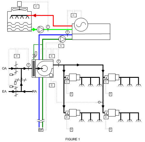


vickers audio,vickers ak sling,vickers auto parts,vickers automotive,vickers audio douglas ga,vickers aircraft,vickers and associates,vickers and white,vickers and academy,vickers av,solenoid actuator,solenoid air valve,solenoid assembly,solenoid autozone,solenoid arduino,solenoid actuator valve,solenoid atv,solenoid armature,solenoid activator,solenoid amazon,valve adjustment,valve adjustment tool,valve actuator,valve adjustment cost,valve adjustment honda,valve anti cheat,valve assembly,valve adapter,valve artifact,valve amplifier,wiring a light switch,wiring a 3 way switch,wiring an outlet,wiring a gfci outlet,wiring a ceiling fan,wiring a switch,wiring a plug,wiring a doorbell,wiring a receptacle,wiring a light fixture,diagram a sentence,diagram a sentence for me,diagram app,diagram a sentence online,diagram as code,diagram and label a section of dna,diagram architecture,diagram art,diagram and explain the endosymbiotic theory,diagram anatomy


