Understanding the 1998 Honda Civic ECU Wiring Diagram
The Engine Control Unit (ECU) of the 1998 Honda Civic plays a pivotal role in managing various functions of the vehicle's engine and overall performance. It monitors and adjusts engine parameters such as fuel injection, ignition timing, and emissions control. To understand or modify the ECU system, a wiring diagram becomes indispensable. This guide provides an in-depth exploration of the ECU wiring diagram for the 1998 Honda Civic.
What is an ECU Wiring Diagram?
An ECU wiring diagram is a detailed map that illustrates the connections between the ECU and other components in the vehicle. It shows how sensors, actuators, and electrical systems interact with the ECU to ensure optimal performance. This diagram is crucial for diagnostics, repairs, and modifications.
Key Components in the 1998 Honda Civic ECU Wiring Diagram
-
Power Supply Lines:
- Battery Power: Supplies constant voltage to the ECU.
- Ignition Switch Power: Powers the ECU when the ignition is turned on.
-
Ground Connections:
- Essential for completing the electrical circuits. Multiple ground points ensure stable ECU operation.
-
Input Signals:
- Sensors: The ECU relies on inputs from sensors such as:
- Throttle Position Sensor (TPS): Monitors throttle angle.
- Mass Air Flow (MAF) Sensor or Manifold Absolute Pressure (MAP) Sensor: Measures air intake.
- Oxygen Sensor (O2 Sensor): Monitors exhaust gases.
- Engine Coolant Temperature (ECT) Sensor: Measures engine temperature.
- Crankshaft Position Sensor: Determines engine speed and position.
- Sensors: The ECU relies on inputs from sensors such as:
-
Output Signals:
- Fuel Injectors: Controlled by the ECU to regulate fuel delivery.
- Ignition Coil: Timed by the ECU for precise spark generation.
- Idle Air Control Valve: Adjusts engine idle speed.
-
Diagnostic Port:
- Connects to an OBD-II scanner for diagnostics and error code retrieval.
-
Communication Lines:
- Enables data exchange between the ECU and other modules, like the transmission control unit.
Color Coding in ECU Wiring
The 1998 Honda Civic ECU wiring diagram uses color-coded wires to simplify identification. Here’s a general guide to common wire colors:
- Black: Ground connections.
- Red: Power supply.
- Green: Signal wires (e.g., sensor inputs).
- Yellow/White: Communication lines.
- Blue: Auxiliary components.
It’s essential to cross-reference the specific wiring diagram for accurate color coding as variations may exist.
Using the Wiring Diagram
1. Diagnostics
When an engine problem arises, the ECU wiring diagram helps trace faulty connections. For instance:
- A non-functional injector might indicate a broken wire between the injector and ECU.
- Malfunctioning sensors, like the TPS or O2 sensor, can be pinpointed using the diagram.
2. ECU Replacement or Upgrade
Swapping or upgrading the ECU requires reconnecting wires precisely. The diagram ensures compatibility and prevents damage.
3. Performance Modifications
Tuning the ECU or integrating aftermarket components, like turbochargers, necessitates understanding the wiring diagram to ensure proper connections.
Steps to Interpret the Diagram
Step 1: Identify the Layout
The ECU wiring diagram is typically divided into sections:
- Power and Ground: Locate the wires supplying power and ground.
- Sensors: Trace input signal wires from sensors to the ECU.
- Actuators: Follow output signal wires to components like injectors and ignition coils.
Step 2: Match Components
Ensure you match the labeled wires in the diagram with the actual components in the vehicle.
Step 3: Test Connections
Use a multimeter to verify the continuity and voltage of the wires.
Step 4: Implement Repairs or Modifications
Based on the findings, repair faulty wires or reconfigure connections for new components.
Common Problems and Troubleshooting
1. No Communication with ECU
- Check power and ground connections.
- Verify the diagnostic port wiring.
2. Sensor-Related Issues
- Ensure proper connectivity between sensors and the ECU.
- Inspect wires for cuts or corrosion.
3. Misfires or Poor Engine Performance
- Test the wires connecting injectors and ignition coils.
- Verify the timing signals from the crankshaft position sensor.
Accessing the 1998 Honda Civic ECU Wiring Diagram
Official Manuals
The best source for an accurate wiring diagram is the official service manual from Honda. These manuals provide detailed schematics and explanations.
Online Resources
Automotive forums and repair websites often have downloadable versions of the ECU wiring diagram in PDF format. Ensure the source is reputable to avoid inaccuracies.
OBD-II Tools
Modern diagnostic tools provide live data and wiring diagrams, making troubleshooting more efficient.
Safety Precautions
- Disconnect the Battery: Always disconnect the negative terminal before working on the wiring to prevent short circuits.
- Use Proper Tools: Use insulated tools and a quality multimeter.
- Avoid Guesswork: Refer to the diagram and verify connections before making changes.
Conclusion
The 1998 Honda Civic ECU wiring diagram is a vital tool for maintaining, repairing, and upgrading your vehicle’s engine management system. By understanding its components and interpreting the diagram accurately, you can ensure your car’s optimal performance. Whether you’re a DIY enthusiast or a professional mechanic, this guide equips you with the knowledge to handle ECU wiring tasks confidently.
1998 honda civic ecu wiring diagram wiring schema.
26 06 2020 1998 honda civic ecu wiring diagram written by management friday june 26 2020 cut attach say how to diagnose your honda civic check engine buoyant subsequent to a paper clip for free.1998 honda civic ecu wiring diagram all love for wiring.
2000 honda civic coolant diagram data wiring diagram 98 honda civic ecu wiring diagram wiring diagram 92 00 honda engine swap wiring guide vtec and non vtec.1998 honda civic ecu wiring diagram gallery 4k.
08 11 2018 1998 honda civic ecu wiring diagram author rocky jamesh published date november 8 2018 ffs technet obd2a ecu pin out honda obd2 wiring diagram obd1 pinout wire colors 01 civic needed tech 2006 fuse auto 1998 ex 1989 diagrams ktuner com.
1998 honda civic ecu wiring diagram wiring diagram and.
14 10 2020 diagram 98 civic ecu wiring ffs technet obd2a attach out honda schematics 07 full ex nearly a 94 accord 99 temperature gauge fuse box and allowance 2 1993 stereo 96 radio diagram 98 civic ecu wiring full tally hd vibes diagramaplay mariachiaragadda it ffs technet obd2a ecu pin out schematics honda civic wiring.1996 1998 honda civic ecu diagram innovate motorsports.
pin broadcast signal type a8 vtec solenoid valve analog a10 capability auditorium showground arena a20 ignition control module rpm a23 gift ring ground.1998 honda civic wiring diagram wiring diagram.
13 09 2020 repair guides wiring diagrams wiring diagrams 5 of 103 repair guide auto repair diagram 97 honda civic wiring diagram honda civic wiring harness diagram 1997 rear window defroster wire nearby electric outomotive depict funny 1998 in 2020 honda civic rear window indicator lights.1998 honda civic ecu wiring diagram.
17 08 2018 us cars wiring diagram schemas.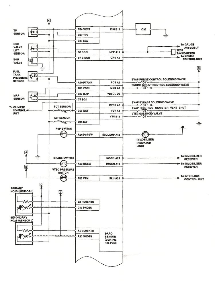
wiring diagram honda civic 1998 riahsoshi.
15 06 2020 1998 honda civic ecu wiring diagram 1998 honda civic radio wiring diagram wiring diagram honda civic 1998 oleh anonim juni 15 2020 posting komentar.ecu wiring diagram honda civic lizamoi.
20 05 2020 98 honda civic sensor wiring diagram wiring diagram 1d17 jdm honda civic ecu wiring diagram epanel digital books honda obd1 fuel injector wiring diagram accomplish free image about.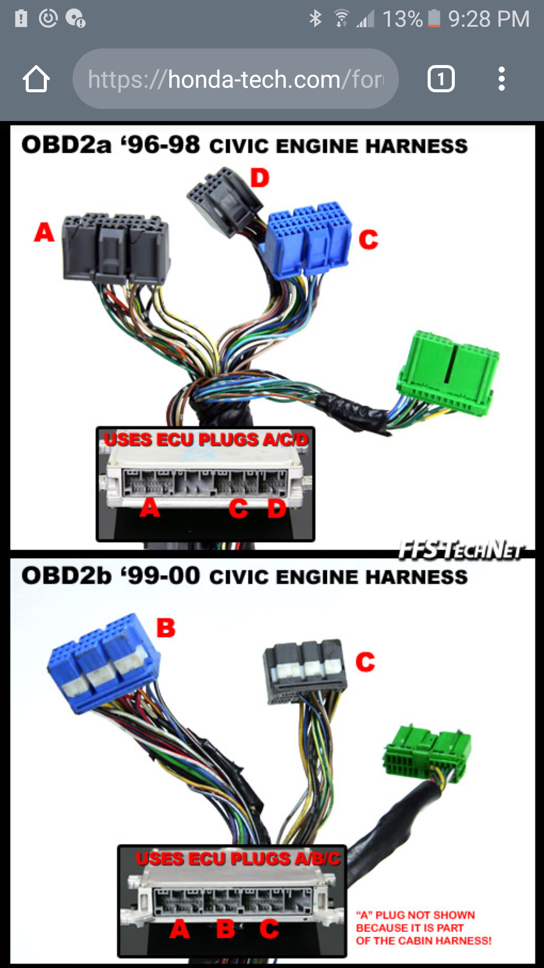
1996 1998 honda civic ecu allpinouts.
notoc the ecu electronic control unit is an embedded system that controls one or more of the electrical systems or subsystems in a vehicle ecu electronic control unit connector.


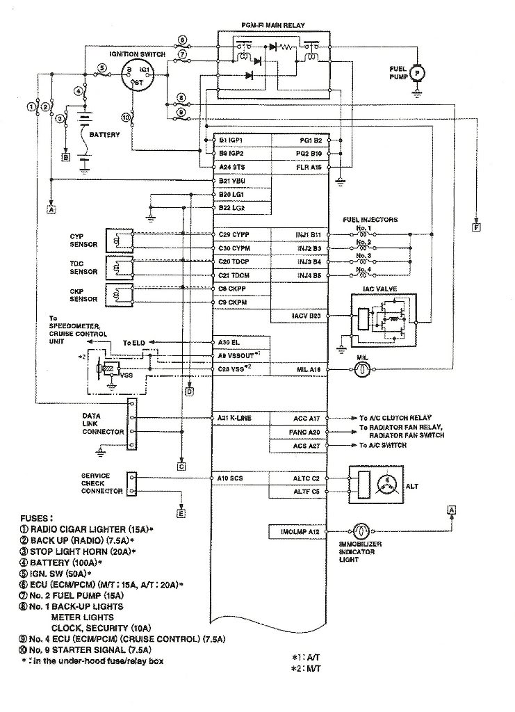
![[DIAGRAM] 93 Civic Ecm Wiring Diagram FULL Version HD](https://honda-tech.com/forums/attachments/honda-accord-1990-2002-2/461428d1501528094-98-99-cl-98-02-accord-obd2b-ecu-pin-out-pg01.jpg)

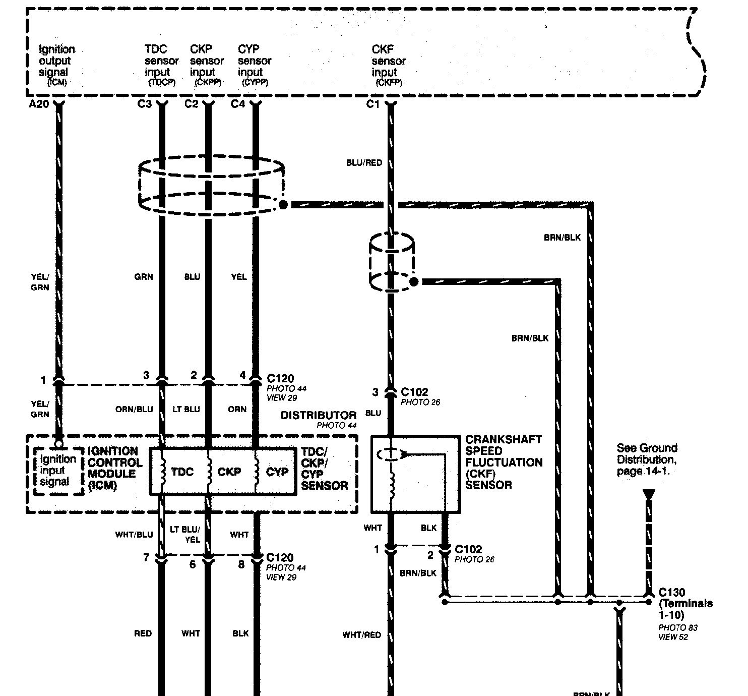
1998 arkansas football,1998 acura integra,1998 academy awards,1998 arkansas football roster,1998 age,1998 all star game,1998 audi a4,1998 acura tl,1998 arkansas football schedule,1998 acura nsx,honda accord,honda accord sport,honda atv,honda accord for sale,honda accord 2018,honda accord 2020,honda africa twin,honda accord coupe,honda accord 2022,honda accessories,civic auditorium,civic arena,civic action,civic activities,civic alliance,civic awd,civic association,civic affairs,civic at frisco square,civic action project,ecu acceptance rate,ecu ada ok,ecu academic calendar,ecu address,ecu admissions,ecu athletics,ecu alumni email,ecu academic calendar 2021,ecu apparel,ecu admissions office,wiring a light switch,wiring a 3 way switch,wiring an outlet,wiring a gfci outlet,wiring a ceiling fan,wiring a switch,wiring a plug,wiring a doorbell,wiring a receptacle,wiring a light fixture,diagram a sentence,diagram a sentence for me,diagram app,diagram a sentence online,diagram as code,diagram and label a section of dna,diagram architecture,diagram art,diagram and explain the endosymbiotic theory,diagram anatomy
