Electric Fence Circuits Schematics: Understanding the Basics and Key Components
Electric fences are a popular and effective solution for securing property, containing livestock, and protecting gardens. They deliver a mild electric shock when touched, which deters animals or intruders from crossing the boundary. However, to ensure that an electric fence operates safely and efficiently, it's essential to understand how to design and wire the system correctly. This is where electric fence circuits schematics come into play.
In this article, we’ll explore the basics of electric fence circuits schematics, break down the critical components involved, and show you how to read and understand these diagrams. We will also explain the key factors to consider when setting up an electric fence system for optimal performance.
What are Electric Fence Circuits Schematics?
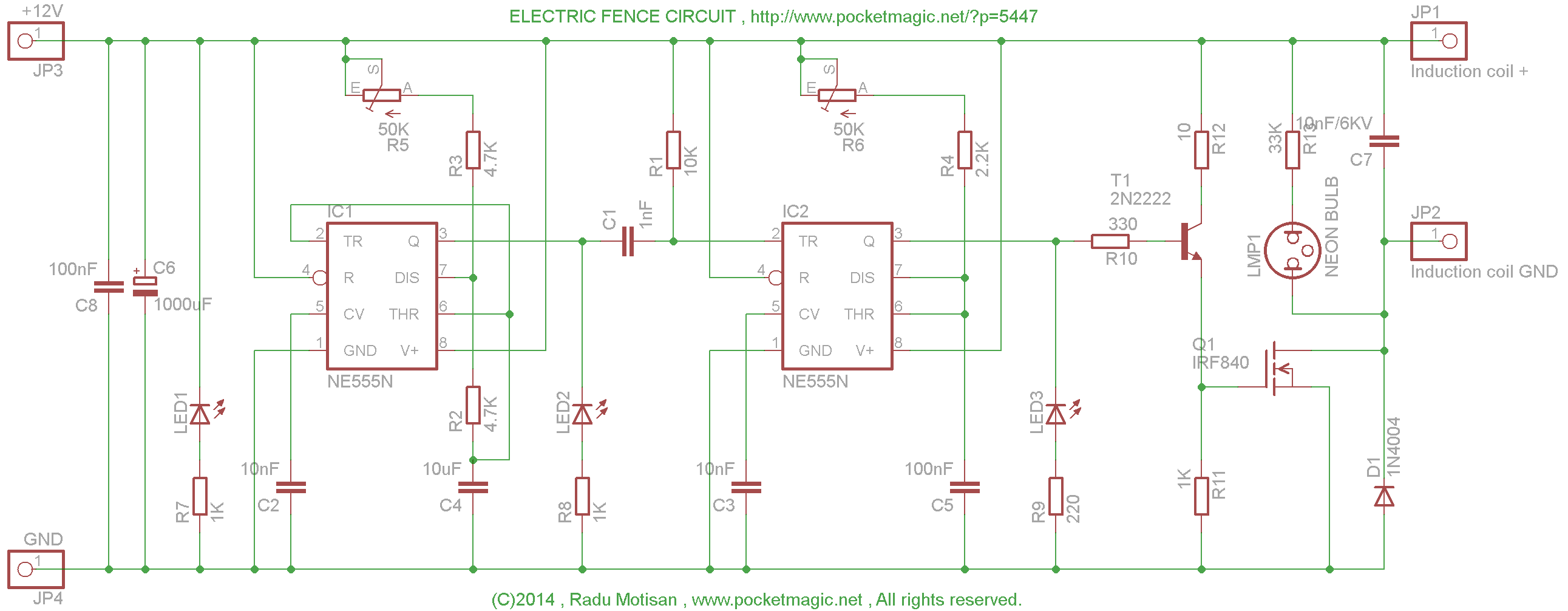
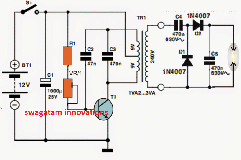
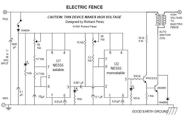
An electric fence circuit schematic is a diagram that visually represents the connections, components, and electrical flow in an electric fence system. It shows how the energizer, fence wiring, grounding system, and other components are wired together. These schematics provide a clear picture of how the electrical current flows through the system and how each part interacts with the others.
A well-designed schematic can help you troubleshoot problems, install a new system, or upgrade an existing fence with confidence. It is a valuable tool for ensuring that your electric fence functions properly, delivering the correct voltage and preventing faults.
Key Components of Electric Fence Circuits
Before we dive into the details of reading electric fence circuit schematics, let’s first understand the critical components involved in an electric fence system. These components will be represented in the schematics.
-
Energizer (Fence Charger):
- The energizer is the heart of the electric fence system. It generates high-voltage electrical pulses and sends them through the fence wire. The energizer is usually connected to an external power source (AC, DC, or battery), which powers the entire system.
- Energizers are typically connected to a grounding system, which helps complete the electrical circuit.
-
Fence Wire:
- The fence wire carries the electric pulse around the perimeter. Different types of wire are used, such as galvanized wire, polywire, or polyrope. The wire must be properly tensioned and insulated to prevent electrical loss and ensure safety.
-
Grounding System:
- The grounding system is vital to the operation of an electric fence. It completes the circuit by providing a return path for the electrical current. Ground rods are driven deep into the earth, and a ground wire connects them to the energizer.
- Without a proper grounding system, the electric fence will not work effectively, and animals may not receive the deterrent shock.
-
Fence Posts and Insulators:
- Fence posts support the wire, while insulators prevent the wire from touching the posts. This ensures that the electrical charge travels through the wire and doesn’t short-circuit to the ground.
- Insulators come in various forms, such as nail-on, screw-on, or clip-on, depending on the type of posts used.
-
Gate Handles (Optional):
- Gate handles allow access through the electric fence while maintaining the electrical current when the gate is closed. The handle is wired in such a way that it ensures the gate is electrically connected to the rest of the system.
-
Fuses and Relays:
- Fuses protect the system from electrical overload, preventing damage to the energizer and other components.
- Relays are used to control the flow of electricity to various parts of the fence, such as activating the energizer or shutting it off when required.
How to Read Electric Fence Circuits Schematics
An electric fence circuit schematic uses standardized symbols to represent the components of the system and the paths that electrical currents take through the system. Here's how to interpret the key elements of a typical schematic:
1. The Energizer:
- In a schematic, the energizer is usually depicted as a box or rectangle labeled "Energizer" or "Fence Charger". The energizer will have connections for positive and negative terminals.
- The positive terminal is connected to the live wire of the fence, while the negative terminal connects to the grounding system.
2. Fence Wire:
- The fence wire is shown as a continuous line that loops around the perimeter of the area being fenced.
- The schematic will show how the wire is connected to the energizer and routed along the fence posts.
3. Grounding System:
- The grounding system is typically represented by a ground symbol (three downward lines) and lines showing the connection between the ground rods and the energizer’s ground terminal.
- This system must be connected properly to ensure that the electrical circuit is complete.
4. Fence Posts and Insulators:
- Fence posts are shown as vertical lines or rectangles, while insulators are depicted as small symbols that appear on the posts. They are positioned along the wire’s path to ensure that the wire remains electrically isolated from the posts.
5. Relays and Fuses:
- Relays are shown as symbols with contacts that open and close when activated. They control the power flow to different parts of the fence.
- Fuses are typically shown as small circles or squares with lines to indicate where the fuse protects the circuit. They prevent overcurrent conditions that could damage components.
6. Gate Handles:
- If your electric fence has a gate, it will be represented as a break in the wire, with the gate handle symbol showing how the wire reconnects when the gate is closed.
Common Types of Electric Fence Circuit Schematics
Here are some of the common configurations you’ll see in electric fence circuit schematics:
1. Basic Electric Fence Circuit:
- This is the most straightforward schematic, with the energizer connected to a single strand of fence wire and a grounding system. It’s used for smaller enclosures or as a simple perimeter barrier.
Key Points in the Schematic:
- Energizer with positive terminal connected to the fence wire.
- Negative terminal connected to the grounding system.
- Fence wire supported by posts and insulators.
2. Multiple Wire Electric Fence Circuit:
- For larger enclosures or containing livestock, you may use multiple strands of wire. A typical schematic shows the energizer connected to several wires, spaced vertically to deter animals from crossing.
Key Points in the Schematic:
- Multiple fence wires connected to the energizer, spaced vertically.
- Grounding system shared by all wires.
- Proper insulation between each wire and the posts.
3. Electric Fence with Gate:
- In a system that includes a gate, the schematic will show how the wire is routed through the gate and connected to a gate handle, maintaining the electrical flow when the gate is closed.
Key Points in the Schematic:
- Gate handle shown as part of the wire circuit.
- Electrical continuity maintained even when the gate is opened or closed.
4. Electric Fence with Solar Energizer:
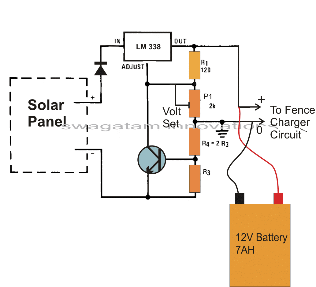
- For remote areas where mains power is not available, solar-powered energizers are used. The schematic shows how the solar panel is connected to the energizer to charge the battery and provide power for the fence.
Key Points in the Schematic:
- Solar panel connected to a battery that powers the energizer.
- Grounding system and wiring similar to other configurations.
Troubleshooting Electric Fence Circuits
If your electric fence isn’t performing as expected, understanding the wiring diagram can help you troubleshoot the issue. Here are some common problems and how to solve them:
1. Low Voltage:
- Check the energizer: Ensure it’s working and properly connected to the power source.
- Inspect the ground system: A poor grounding connection can lead to weak voltage.
- Check for shorts: Inspect the fence wire for places where it may be touching vegetation or posts, which can reduce voltage.
2. No Shock or Inconsistent Shock:
- Inspect fuses and relays: A blown fuse or malfunctioning relay can interrupt the electrical flow.
- Check connections: Loose or corroded connections can prevent the circuit from completing properly.
- Inspect the wire: Ensure the wire is intact and not broken.
3. Animals Getting Through:
- Increase the number of wires: If only one or two wires are used, additional wires can improve containment.
- Check wire height and tension: Ensure the wires are positioned at the correct height and are taut.
Conclusion
Understanding electric fence circuits schematics is crucial for anyone installing or troubleshooting an electric fence. These diagrams provide a clear view of how the components interact, ensuring that the system works effectively and safely. By reading and interpreting these schematics, you can ensure your electric fence is set up properly, prevent electrical faults, and maintain a high level of security for your property, livestock, or garden.
Whether you're installing a basic fence, upgrading to multiple strands, or incorporating solar power, the right circuit schematic can make the process easier and help you keep your electric fence working efficiently. Always remember to follow safety precautions when working with electricity and consult a professional if you’re unsure about your system's wiring.
electric fence circuits schematics wiring view and schematics.
petsafe electric fences this is what you more or less searching for.schematic electric fence circuit diagram.
find instant environment info now complete install an electric fence.electric fence wiring schematic wiring diagram.
improve your matter roi reach a better deal re electric fence wire.
electric fence schematic circuit diagram.
find electric fences search faster better smarter at zapmeta now.gallagher electric fence circuit diagram wiring view and.
19 03 2018 electric fence circuits schematics posted by margaret byrd posted roughly speaking march 19 2018 easy to use electric fencing circuit fence 20kv pulses for how to make a solar charger what is an energizer homemade block diagram window 12v further other perimeter.electric fence wiring diagram wirings diagram.
tg 4883 electric fence circuit diagram then install electric fence wire schematic wiring more ns 8635 electric fence pulser circuit electric fencing schematic wiring more ym 3777 electric fence pulser circuit electric fencing schematic wiring more.simple electric fencing circuit making easy circuits.
03 06 2019 electric fence wiring schematic place the fence controller and its arena system at least 50 ft in order to affect properly every single one electric fence needs a willing dome away from radios and buried telephone wires an electric fence circuit is made regarding a larger scale.
schematic produce develop a homemade fence charger energizer circuit.
16 01 2014 tags electrical symbols electric fence circuit diagram circuit diagram of nearby electronic projects electric fence electric fence schematic diagram metaphor story wiring diagrams electric fence schematic electrical schematic for cars electronics projects electronic circuit diagram how to run an electric fence wire schematic diagram electric fencing symbols for a circuit.a homemade fence charger energizer circuit best electronic.
19 09 2017 gallagher electric fence circuit diagram posted by margaret byrd posted on the order of september 19 2017 electric fence field system circuit diagram energizer block a homemade charger schematic thebackshed com forum when alarm court generator.
electric fence circuits schematics


electric avenue,electric audi,electric air pump,electric atv,electric avenue lyrics,electric airplane,electric acoustic guitar,electric assist bike,electric air compressor,electric atv for adults,fence and deck connection,fence around pool,fence art,fence and deck depot,fence authority,fence alternatives,fence at home depot,fence at lowes,fence and deck direct,fence anchors,circuits and symbols worksheet answers,circuits and shields,circuits are busy,circuits and cables,circuits and electricity,circuits anchor chart,circuits assembly,circuits and systems,circuit analysis,circuits and circuit elements,schematics and blueprints,schematics angular,schematics and diagrams,schematics architecture,schematics always show switches in what position,schematics art,schematics app,schematics alien isolation,schematics arduino,schematics angular material


