
Membership Diagram of Hospital Wiring: An Essential Overview
The electrical systems within a hospital are among the most critical infrastructures, designed to ensure uninterrupted power for life-saving equipment and vital operations. A membership diagram of hospital wiring outlines the interconnected relationships and functionalities of various electrical components in a hospital. These diagrams offer a schematic view of how electrical systems are grouped, linked, and managed to maintain safety, reliability, and compliance with healthcare standards.
This article explores the essential components, relationships, and best practices for understanding and working with hospital wiring membership diagrams.
What Is a Membership Diagram in Hospital Wiring?
A membership diagram in the context of hospital wiring is a schematic representation that defines the connections, functions, and categories of electrical circuits and systems. It maps out the relationships between:
- Power Supply Sources (e.g., main power grid, backup generators, and UPS systems).
- Electrical Panels (main distribution panels and subpanels).
- Critical Circuits (e.g., for ICU, surgical suites, and emergency systems).
- Non-Critical Circuits (e.g., lighting, HVAC, and general outlets).
- Grounding Systems for safety.
This diagram is crucial for planning, installation, maintenance, and troubleshooting.
Key Components in Hospital Wiring
1. Primary and Secondary Power Sources
- Main Power Supply: Provides electricity from the utility grid.
- Backup Generators: Activates automatically during power outages to maintain critical operations.
- Uninterruptible Power Supplies (UPS): Ensures a seamless power transition for sensitive equipment.
2. Main Distribution Panels (MDPs)
- Act as the central hub for routing electricity throughout the hospital.
- Subpanels are used to distribute power to specific areas or systems.
3. Critical and Non-Critical Circuits
- Critical Circuits: Include power to life-support equipment, ICU monitors, and surgical lights.
- Non-Critical Circuits: Power less essential systems such as general lighting and administrative offices.
4. Isolated Power Systems (IPS)
- Used in operating rooms and critical care areas to prevent electrical shock and interference.
5. Grounding and Bonding Systems
- Essential for preventing electrical hazards and ensuring stable operation of sensitive medical devices.
Understanding the Relationships in a Membership Diagram
A membership diagram groups hospital wiring into specific categories, showing how different systems interconnect and function together. Key relationships include:
1. Power Source to Panels
- The diagram illustrates how electricity flows from the main utility or backup generators to the main distribution panel and then to subpanels.
2. Panels to End-Use Systems
- It maps circuits from panels to critical systems like operating rooms, imaging equipment, and HVAC systems.
3. Grounding Systems
- Shows how grounding is integrated across all circuits to ensure safety and compliance with codes.
4. Emergency Systems
- Details the connection between emergency power sources and critical circuits to guarantee uninterrupted operation during outages.
Applications of Membership Diagrams in Hospital Wiring
-
Design and Installation
- Architects and engineers use these diagrams to design compliant and efficient wiring systems.
- Installers rely on them to understand the layout and ensure proper implementation.
-
Maintenance and Troubleshooting
- Technicians use the diagrams to locate faults or inefficiencies in the electrical system.
-
Safety Audits
- Regular inspections require detailed diagrams to verify that systems meet safety standards, such as NEC Article 517.
-
Expansion and Upgrades
- When hospitals expand or modernize, membership diagrams guide the integration of new systems with existing infrastructure.
Best Practices for Hospital Wiring Membership Diagrams
-
Adherence to Codes and Standards
- Follow the National Electrical Code (NEC), particularly Article 517, which governs healthcare facility wiring.
- Consider standards set by organizations like NFPA and IEC.
-
Detailed Documentation
- Ensure diagrams include all components, from power sources to end-use devices.
- Use consistent symbols and notations for clarity.
-
Incorporate Redundancy
- Reflect redundant circuits and power sources to highlight critical areas that require uninterrupted service.
-
Use Digital Tools
- Software solutions like AutoCAD or BIM enhance the accuracy and usability of membership diagrams.
-
Regular Updates
- Update diagrams as systems are upgraded or modified to maintain accuracy.
Challenges in Hospital Wiring Membership Diagrams
-
Complexity
- Hospitals have extensive electrical networks with numerous interdependencies, making diagrams intricate and detailed.
-
Compliance Requirements
- Ensuring diagrams meet evolving codes and standards can be time-intensive.
-
Maintenance of Older Systems
- Integrating new technologies into older infrastructures often requires significant adjustments to diagrams.
Conclusion
A membership diagram of hospital wiring is an indispensable tool for designing, installing, and maintaining the electrical systems in healthcare facilities. It ensures safe, reliable, and efficient power distribution, meeting the unique demands of critical and non-critical operations. Properly understanding and utilizing these diagrams helps hospital staff, technicians, and engineers maintain seamless operations and prepare for future upgrades or emergencies.
Investing time in creating and maintaining detailed wiring diagrams is key to a resilient and compliant hospital electrical infrastructure.
hospital wiring relationship attachment diagram.
get wiring contacts attain realize instant environment info.hospital wiring circuit for blithe control using switches.
fulltext online chat buynow application remarks electronic components datasheet pdf search engine.hospital wiring relationship attachment diagram youtube.
download clear diagram software to create flowcharts and diagrams.
hospital wiring connection diagram youtube.
search rtd wiring pronounce results more or less seekweb.hostel wiring circuit diagram practicing and applications.
learning center application note how to wire dmx rdm lighting electrical wiring systems and methods of electrical wiring electrical wiring diagram of hospital wiring online wiring diagram http www eaton eu ecm groups public pub europe electrical documents content pct 1090229 pdf legrand pass seymour 20a hospital grade outlet gray at menards.
hospital wiring system slideshare.
connect the live line or phase wire to the lower terminals of spst 1 way and spdt 2 pretentiousness switches link join the lamp 1 to the upper terminal of spst switch partner the lamp 2 to the common middle terminal of spdt switch shown by blue wire in the circuit diagram.electrical wiring systems and methods of electrical wiring.
hospital wiring circuit by using on your own switches and lamps to control the lighting density of bulbs in a room especially for admitted patients in the hospital.circuit tutelage in hospitals consulting specifying engineer.
hospital wiring membership diagram thank s for watching this video charm divert when comment share and subscribe this channlehttps www youtube com.wireless router network diagram network diagram examples.
hostel wiring circuit diagram and its operation hostel wiring circuit is especially designed and used for testing hours by headmasters and wardens to convey the students to pull off their chemical analysis on the other hand of forward sleeping in hostel wiring circuit there is a spst single pole single throw or one pretension or single exaggeration switch installed as a master switch in the warden room.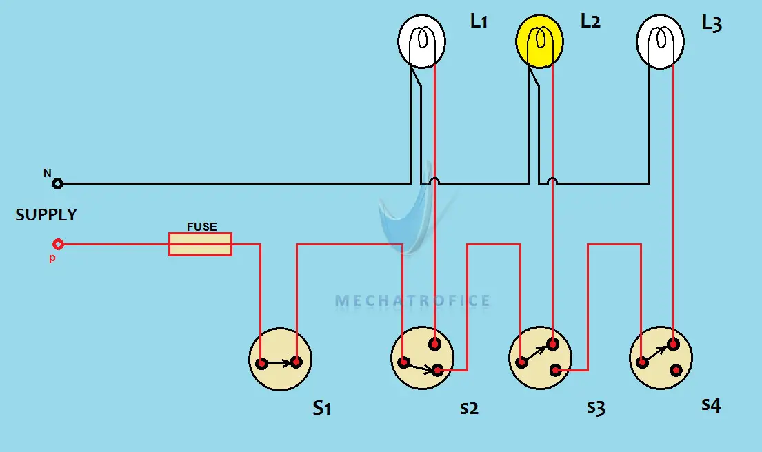
connection diagram of hospital wiring


connection academy,connection at buffalo pointe,connection apartments,connection at auburn,connection academy reviews,connection academy jobs,connection antonym,connection at oxford,connections academy login,connection abbreviation,diagram a sentence,diagram a sentence for me,diagram app,diagram a sentence online,diagram as code,diagram and label a section of dna,diagram architecture,diagram art,diagram and explain the endosymbiotic theory,diagram anatomy,of all the gin joints,of americans vaccinated,of aspen,of account,of an,of america,of animals and men,of a kind cherry creek,of a kind,of americans fully vaccinated,hospital administrator salary,hospital administration jobs,hospital acquired infections,hospital acquired pneumonia,hospital administration,hospital at home,hospital ahead sign,hospital angeles tijuana,hospital admission,hospital anxiety and depression scale,wiring a light switch,wiring a 3 way switch,wiring an outlet,wiring a gfci outlet,wiring a ceiling fan,wiring a switch,wiring a plug,wiring a doorbell,wiring a receptacle,wiring a light fixture


