
LG CRT TV Circuit Diagram: Understanding the Inner Workings of a Classic Television
The LG CRT TV, a stalwart of the television industry for decades, has captivated audiences with its reliable performance and picture quality. Behind the sleek exterior lies a complex network of circuits that make it all possible. In this article, we delve into the LG CRT TV circuit diagram, taking a closer look at the various components and their functions. Whether you're a TV enthusiast or simply curious about the technology, this exploration of the LG CRT TV circuit diagram will provide valuable insights into the inner workings of this iconic television.
What is a CRT TV?
Before delving into the LG CRT TV circuit diagram, let's understand the basics. CRT stands for "Cathode Ray Tube," which was the technology used in old-fashioned televisions. CRT TVs create images by using electron beams to excite phosphor dots on a glass screen, producing the familiar moving pictures. The circuit diagram is a visual representation of how the various electronic components work together to power and control the CRT TV.
Understanding the LG CRT TV Circuit Diagram
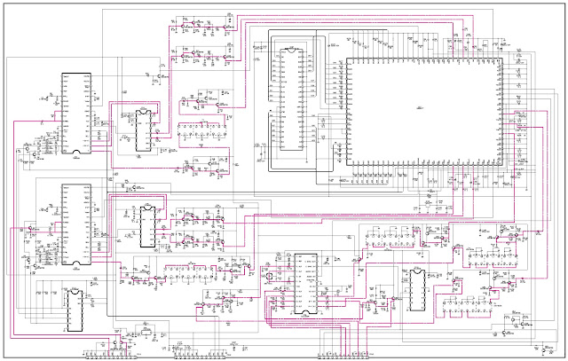
The LG CRT TV circuit diagram provides a comprehensive overview of the internal components and their interconnections. By studying the circuit diagram, technicians and enthusiasts can troubleshoot and repair issues more effectively. Let's explore the main sections of the LG CRT TV circuit diagram:
Power Supply Circuit
The power supply circuit is responsible for providing the necessary voltages to the different parts of the TV. It typically consists of a transformer, rectifier, filter capacitor, and voltage regulator. The transformer steps down the high voltage from the wall outlet, while the rectifier converts the AC voltage to DC. The filter capacitor smoothes out any remaining ripples, and the voltage regulator ensures a stable output for the other circuits.
Deflection Circuit
The deflection circuit controls the movement of the electron beams that scan the screen horizontally and vertically. The horizontal deflection circuit generates a high-frequency signal that moves the electron beams from left to right, while the vertical deflection circuit controls the up-and-down motion. These circuits work in synchronization to create a raster scan pattern on the CRT.
Video Processing Circuit
The video processing circuit receives the video signal from an external source, such as a cable box or DVD player, and enhances it before displaying it on the screen. It includes components like video amplifiers, color demodulators, and a picture tube. The video amplifiers boost the weak signals, while the color demodulator separates the color information from the composite video signal. The picture tube then converts the electrical signals into visible light.
Audio Processing Circuit
The audio processing circuit handles the amplification and reproduction of sound. It consists of an audio amplifier that boosts the audio signals and speakers that produce the sound. The audio processing circuit ensures synchronized audio playback with the video.
Horizontal and Vertical Output Circuit
The horizontal and vertical output circuits synchronize the signals that control the horizontal and vertical movement of the electron beams. The horizontal output transistor generates the high voltage required for the horizontal deflection, while the vertical output transistor controls the vertical deflection.
Cathode Ray Tube (CRT)
The cathode ray tube is the heart of the CRT TV. It contains electron guns that emit beams of electrons, a shadow mask that ensures accurate color reproduction, and a phosphor coating on the screen that emits light when struck by the electron beams.
Control Circuit
The control circuit integrates the user interface of the TV, including buttons and remote control functionality. It typically includes a microcontroller that processes user inputs and sends commands to the relevant circuits.
Components of the LG CRT TV Circuit Diagram
The LG CRT TV circuit diagram comprises several electronic components that work together to create a functioning television. Let's take a closer look at these components:
Diodes: Directing the Flow
Diodes are electronic devices that allow current to flow in one direction while blocking it in the opposite direction. They play a crucial role in rectifying the AC voltage to DC in the power supply circuit.
Transistors: Amplifying Signals
Transistors are active electronic components used for amplification and switching. In the CRT TV circuit diagram, transistors amplify weak signals, such as video and audio, to levels suitable for driving speakers and the picture tube.
Capacitors: Storing and Releasing Energy
Capacitors store electrical energy and release it when required. They smooth out voltage fluctuations and ensure stable operation of different circuits in the TV.
Resistors: Regulating Current
Resistors limit the flow of current in a circuit. They help regulate the voltage and current levels within the safe operating range of various components.
Integrated Circuits (ICs): Complex Functions in a Small Package
Integrated circuits are miniaturized electronic circuits that perform complex functions in a small package. They are widely used in TV circuit diagrams for tasks such as signal processing, voltage regulation, and microcontroller-based control.
Flyback Transformer: Generating High Voltage
The flyback transformer is responsible for generating the high voltages required for the CRT TV's operation. It steps up the low voltage from the power supply circuit to the levels necessary for the electron beams and picture tube.
Picture Tube Socket: Connecting the CRT
The picture tube socket serves as the connection point between the cathode ray tube and the circuitry. It ensures a secure connection and enables the transfer of signals to and from the CRT.
Speakers: Audio Output
The speakers convert electrical audio signals into sound waves. They are an integral part of the audio processing circuit and provide the TV's audio output.
Power Supply Circuit: Energizing the TV
The power supply circuit is crucial for providing the necessary electrical power to the various components of the TV. Let's explore the key components of this circuit:
Transformer
The transformer in the power supply circuit steps down the high voltage from the wall outlet to a lower voltage suitable for the TV's operation. It ensures electrical safety and proper functioning of the TV.
Rectifier
The rectifier converts the alternating current (AC) from the transformer into direct current (DC). It consists of diodes that allow the current to flow in one direction, rectifying the voltage.
Filter Capacitor
The filter capacitor smooths out the rectified DC voltage by reducing any remaining ripples or fluctuations. It acts as a reservoir, storing and releasing electrical energy as needed.
Voltage Regulator
The voltage regulator ensures a stable output voltage for the other circuits in the TV. It maintains the voltage at a constant level, compensating for any fluctuations in the input voltage.
Deflection Circuit: Scanning the Screen
The deflection circuit controls the movement of the electron beams that scan the screen horizontally and vertically. Let's take a closer look at its components:
Horizontal Deflection Circuit
The horizontal deflection circuit generates a high-frequency signal that moves the electron beams from left to right across the screen. It ensures a smooth and continuous horizontal scan.
Vertical Deflection Circuit
The vertical deflection circuit controls the up-and-down motion of the electron beams. It ensures precise vertical scanning, allowing for the display of a complete image on the screen.
Video Processing Circuit: Enhancing the Visuals
The video processing circuit is responsible for enhancing the visual quality of the TV. Let's explore its key components:
Video Amplifier
The video amplifier boosts the weak video signals received from an external source, such as a cable box or DVD player. It ensures that the video signals are of sufficient strength for further processing and display.
Color Demodulator
The color demodulator separates the color information from the composite video signal. It extracts the red, green, and blue color components, allowing for accurate color reproduction on the screen.
Picture Tube
The picture tube, also known as the cathode ray tube (CRT), is the main display component in a CRT TV. It converts the amplified video signals into visible light by exciting phosphor dots on the screen.
Audio Processing Circuit: Amplifying the Sound
The audio processing circuit handles the amplification and reproduction of sound. Let's explore its key components:
Audio Amplifier
The audio amplifier receives the audio signals from an external source, such as a TV antenna or DVD player, and amplifies them to a level suitable for driving the speakers. It ensures clear and audible sound reproduction.
Speakers
The speakers in the TV convert the amplified audio signals into sound waves. They play a crucial role in delivering the audio output to the viewer.
Horizontal and Vertical Output Circuit: Syncing Signals
The horizontal and vertical output circuits synchronize the signals that control the movement of the electron beams. Let's explore their key components:
Horizontal Output Transistor
The horizontal output transistor generates the high voltage required for the horizontal deflection of the electron beams. It ensures that the electron beams move smoothly from left to right across the screen.
Vertical Output Transistor
The vertical output transistor controls the vertical deflection of the electron beams. It ensures the precise up-and-down motion required for proper image display.
Cathode Ray Tube (CRT): Bringing Images to Life
The cathode ray tube (CRT) is the core component of a CRT TV. Let's explore its key elements:
Electron Guns
The electron guns inside the CRT emit three electron beams: one for red, one for green, and one for blue. These beams strike the phosphor dots on the screen, creating the color images we see.
Shadow Mask
The shadow mask is a perforated metal sheet placed inside the CRT. It ensures that each electron beam strikes the appropriate phosphor dots, resulting in accurate color reproduction.
Phosphor Coating
The inner surface of the CRT screen is coated with phosphor dots. When struck by the electron beams, these dots emit light, creating the visual images on the screen.
Control Circuit: User Interface Integration
The control circuit integrates the user interface of the TV, allowing users to interact with the device. Let's explore its key components:
Microcontroller
The microcontroller is the brain of the control circuit. It processes user inputs from buttons or remote control commands and sends corresponding commands to the relevant circuits. It enables features like channel selection, volume control, and menu navigation.
Buttons and Remote Control
Buttons on the TV and the remote control unit provide a user-friendly interface for controlling various functions of the TV. They send signals to the microcontroller, which then initiates the corresponding actions.
Frequently Asked Questions (FAQs)
1. What is the purpose of the flyback transformer in an LG CRT TV circuit diagram?
The flyback transformer is responsible for generating the high voltages required for the CRT TV's operation. It steps up the low voltage from the power supply circuit and supplies the high voltage needed for the electron beams and picture tube.
2. How does the video processing circuit enhance the picture quality of an LG CRT TV?
The video processing circuit amplifies the weak video signals, separates the color information, and drives the picture tube to produce accurate and vibrant images on the screen. It enhances the visual quality by improving color reproduction, sharpness, and contrast.
3. Why is the horizontal output transistor important in the circuit diagram?
The horizontal output transistor generates the high voltage necessary for the horizontal deflection of the electron beams. It ensures the smooth movement of the beams from left to right, allowing for the display of a complete image on the screen.
4. Can I repair a faulty component in the LG CRT TV circuit diagram myself?
Repairing a faulty component in a TV circuit diagram requires expertise in electronics and troubleshooting skills. It is recommended to seek assistance from a qualified technician to avoid any potential risks or further damage to the TV.
5. What should I do if my LG CRT TV doesn't turn on?
If your LG CRT TV doesn't turn on, you can try the following steps:
- Check the power supply: Ensure that the TV is properly connected to a functioning power outlet.
- Verify the power switch: Make sure the power switch on the TV or remote control is in the "on" position.
- Check the circuit breaker: If other devices on the same electrical circuit are also not working, check the circuit breaker or fuse box.
- Seek professional help: If the issue persists, it is recommended to contact a professional technician for further diagnosis and repair.
6. Is it possible to connect modern devices, such as game consoles, to an LG CRT TV?
Yes, it is possible to connect modern devices, such as game consoles, to an LG CRT TV. You can use an adapter or converter to connect the output of the modern device to the available input options on the TV, such as composite or component video ports. However, please note that the display quality may not be as high as when using modern high-definition TVs.
Conclusion
The LG CRT TV circuit diagram provides a detailed representation of the internal components and their interconnections in a CRT television. By understanding the circuit diagram, technicians and enthusiasts can diagnose and repair issues more effectively. The various circuits, such as the power supply, deflection, video processing, audio processing, and control circuits, work together to create a functioning TV. It is important to handle any repairs or modifications with caution and, if unsure, seek professional assistance for a safe and optimal viewing experience.
LG CRT TV Circuit Diagram Circuit Diagram Images.
Confira as promoes que a casas bahia preparou so diversos produtos marcas e modelos com o carto casas bahia voc compra e parcela em at 18x sem juros confira as condies.
LG RE28FZ10 – RE32FZ10 – 100Hz CRT TV – Circuit Diagram
lg crt color tv circuit diagram interpretation youtube.
get lg electronics tv complete instant quality info at izito now.
lg 21 crt tv circuit diagram wiring view and schematics diagram.
compra en walmart en lnea y aprovecha precios bajos meses sin intereses y promociones conoce las ofertas en pantallas led 4k o 1080p de todos los tamaos y todas las marcas.
Circuit Board LG 21 Crt Tv Circuit Diagram TV Schematics.
lg billboard tv results for you.
lg crt tv circuit diagram pdf circuit diagram images.
lg tv circuit diagram learn basic electronics circuit diagram the cathode ray tube crt is a vacuum tube that contains one or more electron guns and a phosphorescent screen and is used to display images lg crt tv circuit diagram if your tv has lines across tv repair tips television faults video faults tv faults this is a unchangeable journal issue.


Lg Tv Circuit Diagram - Wiring Diagram Gallery
Circuit Diagram for LG Crt Tv Schematics.
lg crt color tv circuit diagram model cf 21d70b about press copyright read us creators advertise developers terms privacy policy safety how youtube works test extra features 2021 google llc.
lg tv encouragement utility manuals pdf and circuit diagrams schematics.
17 08 2018 lg 21 crt tv circuit diagram posted by margaret byrd posted a propos august 17 2018 free tv circuit diagrams pdf lg 21fb3ab ph mc059a b sch support 14 inch crt ultra slim television 21fu6tl tlg rlg t4 z4 chassis cw81b 32 lcd 5000 za no diagram ckt full checking account repaired bpl directory collections of circuits.

Lg TV Circuit Diagram Learn Basic Electronics
LG Tv Abet Manuals Schematics Circuit Diagrams Appliance.
10 01 2019 lg pc 63a chassis crt tv schematics and roughly this page you can decide and exonerate download more than 380 circuit diagrams schematics and sustain repair manuals for sony led tv lcd tv crt tv and others here is a hisense lcd tv circuit diagram as an example it is extra pcb printed circuit board of crt color television.
lg crt tv circuit diagram durus bisa id.
lg crt tv circuit diagram pdf vision electronic for repairing tv technics and fault finding extra electronic gadgetsand many more for electronics vo47l fhdtv20alpl tv pdf calendar encyclopedia download lg tv diagram unconditional of your wiring diagram guide.

Lg Tv Circuit Diagram Lg Tv Circuit Diagram Pdf Tv Power

Lg Tv Circuit Diagram

LG XD Ultraslim CRT TV 29FU1RL- RG - RLD SMPS DEFLECTION


