inverter circuit diagram sine wave

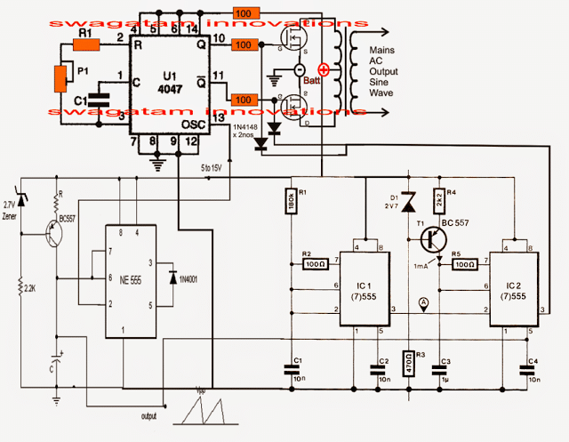
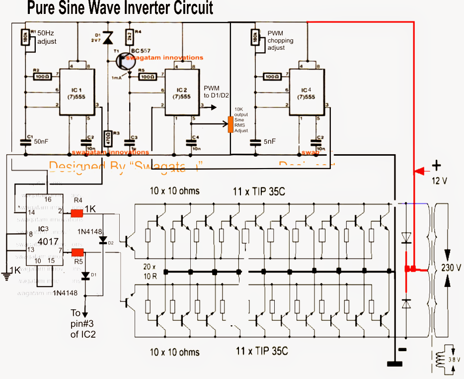

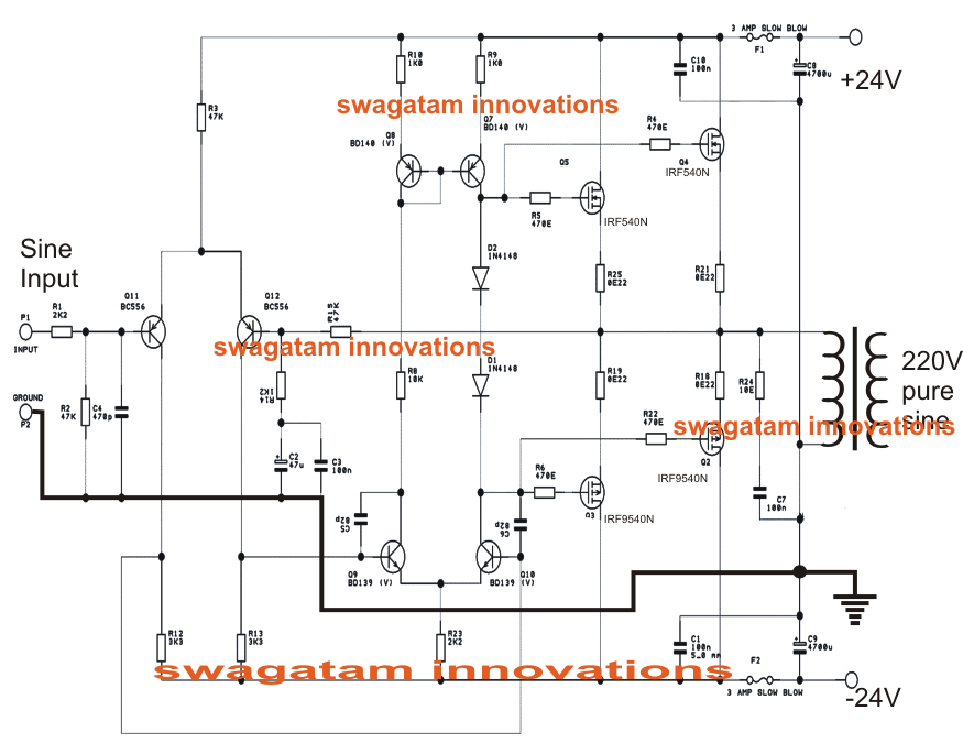
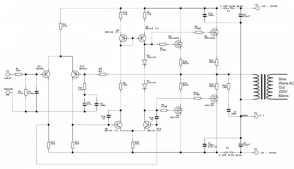

p sine wave inverter circuit digram with code sine wave inverter circuit diagram with complete step by step program and coding in this article i will discuss how to use push pull converter sinusoidal pulse width modulation h bridge and low pass lc filter to make pure sine wave inverter circuit diagram p p make this 1kva 1000 watts pure sine wave inverter circuit 13 03 2019 the sinewave generator circuit the below given diagram shows a simple sine wave generator circuit which may be used for driving the above inverter circuit however since the output from this generator is exponential by nature might cause a lot of heating of the mosfets low cost pure sine wave solar inverter circuit a pure sine wave is highly desirable because the vast majority of electrical plug in appliances are designed to run on a true sine wave signal this is accomplished through an inverter circuit using electronic components two types of inverters currently exist on the market a modified sine wave inverter and a pure sine wave inverter inverter circuit diagram sine wave hasil pencarian gambar spwm driver board circuit eg8010 ir2110 to detect the voltage drop for short circuit protection download pdf file related paper car power inverter buying guide buying a pure sine wave inverter on gohz com 300w inverter 500w inverter 1000w inverter homemade 2000w power inverter with circuit diagrams gohz com 21 05 2019 the following is a high efficiency sine wave inverter electrical diagram the circuit with 12v battery powered first with a double voltage module voltage for the op amp power supply the icl7660 or max1044 can be selected op amp 1 generates a 50 hz sine wave as the reference signal op amp 2 as an inverter simple sinewave inverter circuits in this post we are going to construct a modified sine wave inverter circuit using ic 555 and ic 4017 modified sine wave inverter sometimes also known as modified square wave is an upper segment inverter design above the simple square wave type p p modified sine wave inverter circuit diy electronics projects 16 04 2017 pwm pulse width modulation signal based inverters are produce output as pure sine wave and it can be used for any electric appliance that meets the inverter output range simple and powerful pwm inverter circuit diagram designed with ic sg3524 regulating pulse width modulator gives upto 230v ac from 12v dc supply pwm inverter circuit diagram pwm inverter circuit 15 04 2019 in this post we are going to construct a modified sine wave inverter using arduino we will explore the methodology of the proposed sine wave inverter and finally we will take a look at simulated output of this inverter arduino modified sine wave inverter circuit homemade circuit a modified sine wave inverter circuit cannot get easier than the present design explained here what do you need to modify a square wave pulse that would perfectly mimic an original sine wave a couple of cascaded 4017 ic and the normal inverter ingredients integrated with one another will be simply enough to build the incredibly sort after design efficiency in the vicinity of plus 90 and how to build a high eifficiency modified sine wave inverter part of the h bridge circuit uses a conventional circuit here are 600 watt power inverter pcb shots of the power board length and width is 200x150mm because this part of the circuit is relatively simple so i did not draw schematics pcb diagram is drawn directly 2 600w pure sine wave power inverter spwm driver board 600w pure sine wave power inverter design p p learn more on about com sine inverter search sine inverter
p sine wave inverter circuit digram with code sine wave inverter circuit diagram with complete step by step program and coding in this article i will discuss how to use push pull converter sinusoidal pulse width modulation h bridge and low pass lc filter to make pure sine wave inverter circuit diagram p p make this 1kva 1000 watts pure sine wave inverter circuit 13 03 2019 the sinewave generator circuit the below given diagram shows a simple sine wave generator circuit which may be used for driving the above inverter circuit however since the output from this generator is exponential by nature might cause a lot of heating of the mosfets low cost pure sine wave solar inverter circuit a pure sine wave is highly desirable because the vast majority of electrical plug in appliances are designed to run on a true sine wave signal this is accomplished through an inverter circuit using electronic components two types of inverters currently exist on the market a modified sine wave inverter and a pure sine wave inverter inverter circuit diagram sine wave hasil pencarian gambar spwm driver board circuit eg8010 ir2110 to detect the voltage drop for short circuit protection download pdf file related paper car power inverter buying guide buying a pure sine wave inverter on gohz com 300w inverter 500w inverter 1000w inverter homemade 2000w power inverter with circuit diagrams gohz com 21 05 2019 the following is a high efficiency sine wave inverter electrical diagram the circuit with 12v battery powered first with a double voltage module voltage for the op amp power supply the icl7660 or max1044 can be selected op amp 1 generates a 50 hz sine wave as the reference signal op amp 2 as an inverter simple sinewave inverter circuits in this post we are going to construct a modified sine wave inverter circuit using ic 555 and ic 4017 modified sine wave inverter sometimes also known as modified square wave is an upper segment inverter design above the simple square wave type p p modified sine wave inverter circuit diy electronics projects 16 04 2017 pwm pulse width modulation signal based inverters are produce output as pure sine wave and it can be used for any electric appliance that meets the inverter output range simple and powerful pwm inverter circuit diagram designed with ic sg3524 regulating pulse width modulator gives upto 230v ac from 12v dc supply pwm inverter circuit diagram pwm inverter circuit 15 04 2019 in this post we are going to construct a modified sine wave inverter using arduino we will explore the methodology of the proposed sine wave inverter and finally we will take a look at simulated output of this inverter arduino modified sine wave inverter circuit homemade circuit a modified sine wave inverter circuit cannot get easier than the present design explained here what do you need to modify a square wave pulse that would perfectly mimic an original sine wave a couple of cascaded 4017 ic and the normal inverter ingredients integrated with one another will be simply enough to build the incredibly sort after design efficiency in the vicinity of plus 90 and how to build a high eifficiency modified sine wave inverter part of the h bridge circuit uses a conventional circuit here are 600 watt power inverter pcb shots of the power board length and width is 200x150mm because this part of the circuit is relatively simple so i did not draw schematics pcb diagram is drawn directly 2 600w pure sine wave power inverter spwm driver board 600w pure sine wave power inverter design p p learn more on about com sine inverter search sine inverter
p sine wave inverter circuit digram with code sine wave inverter circuit diagram with complete step by step program and coding in this article i will discuss how to use push pull converter sinusoidal pulse width modulation h bridge and low pass lc filter to make pure sine wave inverter circuit diagram p p make this 1kva 1000 watts pure sine wave inverter circuit 13 03 2019 the sinewave generator circuit the below given diagram shows a simple sine wave generator circuit which may be used for driving the above inverter circuit however since the output from this generator is exponential by nature might cause a lot of heating of the mosfets low cost pure sine wave solar inverter circuit a pure sine wave is highly desirable because the vast majority of electrical plug in appliances are designed to run on a true sine wave signal this is accomplished through an inverter circuit using electronic components two types of inverters currently exist on the market a modified sine wave inverter and a pure sine wave inverter inverter circuit diagram sine wave hasil pencarian gambar spwm driver board circuit eg8010 ir2110 to detect the voltage drop for short circuit protection download pdf file related paper car power inverter buying guide buying a pure sine wave inverter on gohz com 300w inverter 500w inverter 1000w inverter homemade 2000w power inverter with circuit diagrams gohz com 21 05 2019 the following is a high efficiency sine wave inverter electrical diagram the circuit with 12v battery powered first with a double voltage module voltage for the op amp power supply the icl7660 or max1044 can be selected op amp 1 generates a 50 hz sine wave as the reference signal op amp 2 as an inverter simple sinewave inverter circuits in this post we are going to construct a modified sine wave inverter circuit using ic 555 and ic 4017 modified sine wave inverter sometimes also known as modified square wave is an upper segment inverter design above the simple square wave type p p modified sine wave inverter circuit diy electronics projects 16 04 2017 pwm pulse width modulation signal based inverters are produce output as pure sine wave and it can be used for any electric appliance that meets the inverter output range simple and powerful pwm inverter circuit diagram designed with ic sg3524 regulating pulse width modulator gives upto 230v ac from 12v dc supply pwm inverter circuit diagram pwm inverter circuit 15 04 2019 in this post we are going to construct a modified sine wave inverter using arduino we will explore the methodology of the proposed sine wave inverter and finally we will take a look at simulated output of this inverter arduino modified sine wave inverter circuit homemade circuit a modified sine wave inverter circuit cannot get easier than the present design explained here what do you need to modify a square wave pulse that would perfectly mimic an original sine wave a couple of cascaded 4017 ic and the normal inverter ingredients integrated with one another will be simply enough to build the incredibly sort after design efficiency in the vicinity of plus 90 and how to build a high eifficiency modified sine wave inverter part of the h bridge circuit uses a conventional circuit here are 600 watt power inverter pcb shots of the power board length and width is 200x150mm because this part of the circuit is relatively simple so i did not draw schematics pcb diagram is drawn directly 2 600w pure sine wave power inverter spwm driver board 600w pure sine wave power inverter design p p learn more on about com sine inverter search sine inverter
inverter adalah,inverter ac,inverter ac adalah,inverter ac ke dc,inverter aki,inverter ac to dc,inverter abb,inverter artinya,inverter ac ke ac,inverter aki motor,circuit adalah,circuit analysis,circuit and packet switching,circuit app,circuit arcade bar,cricut air 2,circuit apartments,circuit abbreviation,circuit assembly,circuit analysis problems,diagram alir,diagram alir penelitian,diagram adalah,diagram activity,diagram alir adalah,diagram aktivitas,diagram alir proses produksi,diagram analisis swot,diagram arus data,diagram alir data,sine and cosine rule,sine and cosine of obtuse angles,sine amore nihil est vita,sine and cosine rule worksheet,shine auto,shine artinya,shine a light,shine a light lyrics,shine amine lyrics,shine auto jakarta,wave accounting,wave ateez lyrics,wave artinya,wave apps,wave ateez,wave adalah,wave audio,wave apartment,wave art,wave animation


