
Table of Contents
- Introduction
- Overview of Inverter Circuit
- Components Required
- Circuit Diagram
- Working Principle
- Step-by-Step Operation
- SG3524 IC Features
- Advantages of Using SG3524
- PWM Generation
- Protection Mechanisms
- Efficiency and Power Output
- Design Considerations
- Troubleshooting Tips
- Applications of SG3524 Inverter Circuit
- Conclusion
- Frequently Asked Questions (FAQs)
1. Overview of Inverter Circuit
2. Components Required
- SG3524 integrated circuit
- Power MOSFETs (Metal-Oxide-Semiconductor Field-Effect Transistors)
- Resistors and capacitors
- Inductor and transformer
- Diodes
- Heat sink
- PCB (Printed Circuit Board)
- Power source (DC voltage)
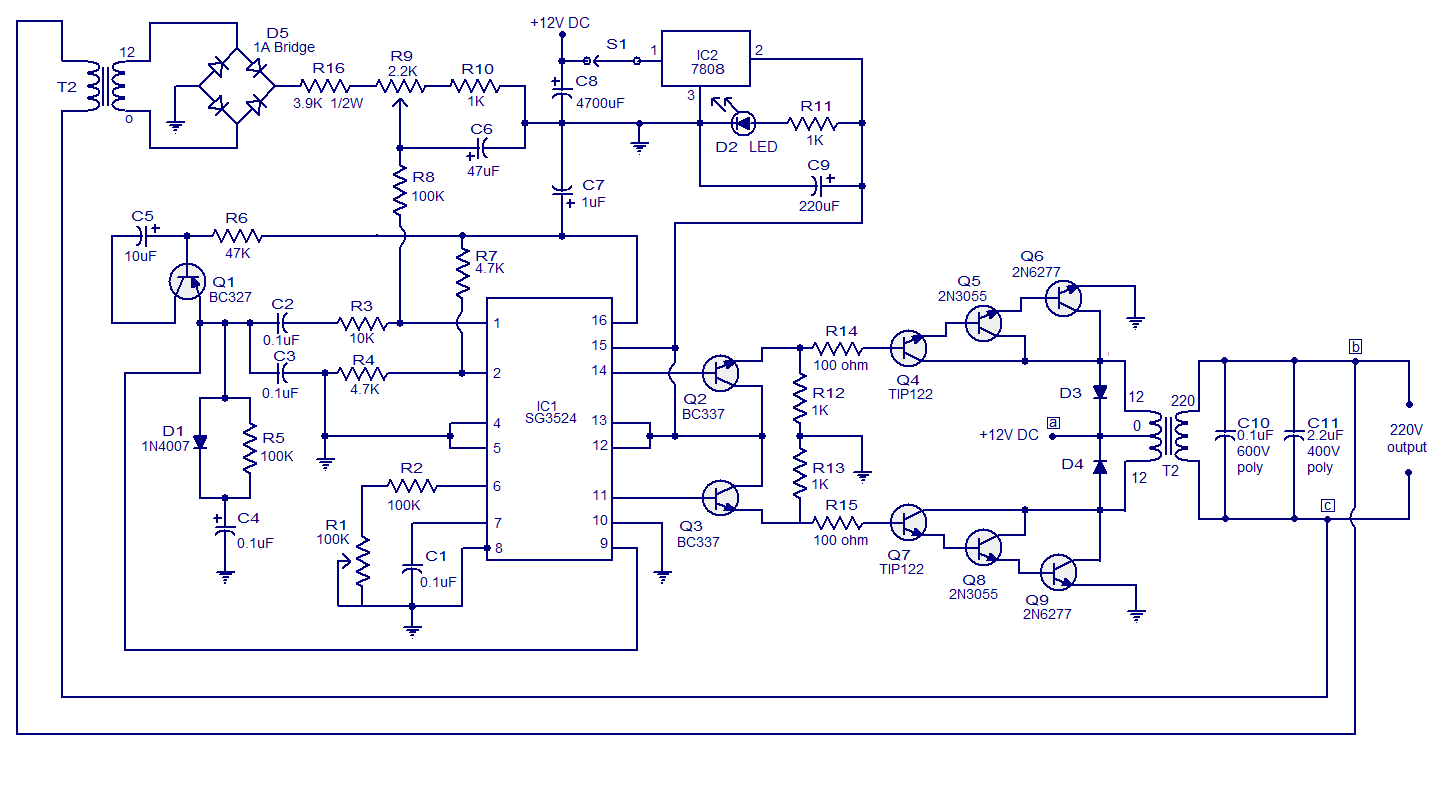
3. Circuit Diagram
4. Working Principle
- Step 1: Power Supply - The DC power source supplies power to the inverter circuit.
- Step 2: Oscillator - The SG3524 IC contains an oscillator circuit that generates a high-frequency square wave signal.
- Step 3: PWM Generation - The square wave signal from the oscillator is fed into the PWM generator of the SG3524.
- Step 4: Error Amplifier - The error amplifier compares the reference voltage with the feedback voltage to generate an error signal.
- Step 5: PWM Control - The error signal is used to control the width of the PWM signal generated by the SG3524.
- Step 6: MOSFET Driver - The PWM signal is then amplified by the MOSFET driver and applied to the MOSFETs.
- Step 7: Power Conversion - The MOSFETs switch on and off based on the PWM signal, converting the DC power into AC power.
- Step 8: Filtering - The AC output is filtered using an inductor and transformer to remove any harmonic distortion.
- Step 9: Output Stage - The filtered AC output is then fed to the load or connected appliances.
5. Step-by-Step Operation
- The power supply provides a DC voltage to the circuit.
- The oscillator circuit in the SG3524 generates a square wave signal with a frequency determined by external components.
- The PWM generator in the SG3524 IC generates a square wave signal with a frequency determined by external components.
- The error amplifier compares the reference voltage with the feedback voltage to produce an error signal.
- The error signal controls the width of the PWM signal generated by the SG3524, regulating the output voltage and frequency.
- The MOSFET driver amplifies the PWM signal and applies it to the MOSFETs.
- The MOSFETs, acting as switches, turn on and off according to the PWM signal, converting the DC power into AC power.
- The AC output is then filtered using an inductor and transformer to remove harmonic distortion and obtain a cleaner waveform.
- The filtered AC output is ready to be used by connected appliances or loads.
6. SG3524 IC Features
- Wide input voltage range
- Adjustable frequency and duty cycle
- High accuracy and stability
- Built-in oscillator and PWM generator
- Error amplifier for precise control
- Overcurrent and short-circuit protection
7. Advantages of Using SG3524
- High efficiency in converting DC to AC power
- Reliable and stable performance
- Flexibility in adjusting frequency and duty cycle
- Protection mechanisms for safe operation
- Compatibility with various load types
- Cost-effective solution for inverter applications
8. PWM Generation
9. Protection Mechanisms
10. Efficiency and Power Output
11. Design Considerations
- Load requirements: Determine the power rating, voltage, and frequency needed for the connected loads.
- Component selection: Choose MOSFETs, capacitors, and inductors with suitable ratings for efficient and reliable operation.
- Heat dissipation: Incorporate proper heat sinks and cooling mechanisms to manage the heat generated during operation.
- PCB layout: Optimize the layout to minimize noise, ensure proper grounding, and maintain signal integrity.
- Safety measures: Implement appropriate protection circuits to prevent damage to the circuit and ensure user safety.
12. Troubleshooting Tips
- Check the power supply: Ensure that the DC power source is providing the correct voltage and is stable.
- Inspect the connections: Verify all the connections between the components, ensuring they are secure and free from loose connections or short circuits.
- Test the SG3524 IC: Check if the IC is functioning properly by measuring the output signals from the oscillator, PWM generator, and error amplifier.
- Verify component ratings: Ensure that the MOSFETs, capacitors, and inductors are within the recommended ratings for your circuit.
- Examine heat dissipation: Inspect the heat sinks and cooling mechanisms to prevent overheating of the components.
- Review PCB layout: Double-check the PCB layout for any design flaws, such as incorrect trace connections or insufficient grounding.
- Analyze feedback mechanism: Verify the feedback mechanism that provides voltage regulation and stability to the circuit.
- Consider external factors: Evaluate any external factors that could affect the circuit's performance, such as environmental temperature or electromagnetic interference.
- If the troubleshooting steps do not resolve the issue, consult the datasheet of the SG3524 IC and seek expert advice for further assistance.
13. Applications of SG3524 Inverter Circuit
- Residential power backup systems
- Solar power inverters
- Uninterruptible Power Supply (UPS) units
- Electric vehicle inverters
- Industrial power systems
- Portable electronic devices
- The versatility and reliability of the SG3524 make it a popular choice for both small-scale and large-scale inverter applications.
Conclusion
Frequently Asked Questions (FAQs)
inverter circuit diagram using sg3524


p simple pwm inverter circuit diagram using pwm chip sg3524 04 09 2012 simple pwm inverter circuit diagram using pwm chip sg3524 gallery of electronic circuits and projects providing lot of diy circuit diagrams robotics microcontroller projects electronic development tools p p inverter circuit using ic sg3524 making easy circuits 10 01 2018 inverter circuit using ic sg3524 last updated on january 10 2018 by admin 15 comments this design is easy to build the output power of 150w the present simple inverter circuit using ic sg 3524 design frequency of about 300hz the purpose is to reduce the volume of the inverter transformer the weight the output waveform is a square wave 250w 5000w sg3524 dc ac inverter circuit electronics projects sg3524 pwm control ic based on the dc to ac inverter circuit transformer change and the number of transistors compared to the 250w 5000w power between can give to developing an open circuit and adding a lot can be done from the simplest low battery my warning already authors add this to a very simple inverter circuit according to the superior inverter circuit diagram using sg3524 hasil pencarian gambar 16 04 2017 pwm pulse width modulation signal based inverters are produce output as pure sine wave and it can be used for any electric appliance that meets the inverter output range simple and powerful pwm inverter circuit diagram designed with ic sg3524 regulating pulse width modulator gives upto 230v ac from 12v dc supply pwm inverter circuit diagram pwm inverter circuit 25 09 2019 hello sir i actually built the above inverter circuit using ic sg3524 and 555 timer as the sine wave generator i feed the 555 timer stage with 5v beside 8v fed to the ic sg3524 however the pwm from ic sg3524 is being blocked by the collectors of the bc547 transistors at the bases of the power stage transistors 3 high power sg3525 pure sinewave inverter circuits homemade 250w pwm inverter circuit sg3524 a 250w pwm inverter circuit built around ic sg3524 is shown here sg3524 is an integrated switching regulator circuit that has all essential circuitry required for making a switching regulator in single ended or push pull mode p p pwm inverter circuit based on sg3524 12v input 220v output here is the circuit idea to build a simple pwm inverter circuit based on ic sg2524 with circuit diagram and working the sg3524 ic chips is a fixed frequency pwm pulse width modulation voltage regulator control circuit simple pwm inverter circuit diagram using pwm chip sg3524 dear friend i am responding to your quest for circuit design using sg3524n for inverter sg3524n is a pwm ic design circuitry that can be use in most electronic design such as inverters regulated power supply and so on when use for inverter it gives a purer modified square wave pwm which is a good approximation of sine wave inverter circuit using sg3524 cr4 discussion thread 02 01 2014 12v to 230v inverter circuit schematic using pulse width modulator ic sg3525 khaleel january 2 2014 so far we have published so many inverter circuits here at circuitsgallery and now i think it s time for me to introduce another one that has more inverter efficiency 12v to 230v inverter circuit schematic using pulse width 11 10 2017 the main feature of this inverter is this is a pwm based circuit and output voltage stables at any load same thing that happens to smps pwm inverter circuit diagram parts list i c sg3524 x1 15 total 12 pcs resistor 6 pwm inverter circuit 500 watt low cost circuits diy p p octopart component search find sg3524

p simple pwm inverter circuit diagram using pwm chip sg3524 04 09 2012 simple pwm inverter circuit diagram using pwm chip sg3524 gallery of electronic circuits and projects providing lot of diy circuit diagrams robotics microcontroller projects electronic development tools p p inverter circuit using ic sg3524 making easy circuits 10 01 2018 inverter circuit using ic sg3524 last updated on january 10 2018 by admin 15 comments this design is easy to build the output power of 150w the present simple inverter circuit using ic sg 3524 design frequency of about 300hz the purpose is to reduce the volume of the inverter transformer the weight the output waveform is a square wave 250w 5000w sg3524 dc ac inverter circuit electronics projects sg3524 pwm control ic based on the dc to ac inverter circuit transformer change and the number of transistors compared to the 250w 5000w power between can give to developing an open circuit and adding a lot can be done from the simplest low battery my warning already authors add this to a very simple inverter circuit according to the superior inverter circuit diagram using sg3524 hasil pencarian gambar 16 04 2017 pwm pulse width modulation signal based inverters are produce output as pure sine wave and it can be used for any electric appliance that meets the inverter output range simple and powerful pwm inverter circuit diagram designed with ic sg3524 regulating pulse width modulator gives upto 230v ac from 12v dc supply pwm inverter circuit diagram pwm inverter circuit 25 09 2019 hello sir i actually built the above inverter circuit using ic sg3524 and 555 timer as the sine wave generator i feed the 555 timer stage with 5v beside 8v fed to the ic sg3524 however the pwm from ic sg3524 is being blocked by the collectors of the bc547 transistors at the bases of the power stage transistors 3 high power sg3525 pure sinewave inverter circuits homemade 250w pwm inverter circuit sg3524 a 250w pwm inverter circuit built around ic sg3524 is shown here sg3524 is an integrated switching regulator circuit that has all essential circuitry required for making a switching regulator in single ended or push pull mode p p pwm inverter circuit based on sg3524 12v input 220v output here is the circuit idea to build a simple pwm inverter circuit based on ic sg2524 with circuit diagram and working the sg3524 ic chips is a fixed frequency pwm pulse width modulation voltage regulator control circuit simple pwm inverter circuit diagram using pwm chip sg3524 dear friend i am responding to your quest for circuit design using sg3524n for inverter sg3524n is a pwm ic design circuitry that can be use in most electronic design such as inverters regulated power supply and so on when use for inverter it gives a purer modified square wave pwm which is a good approximation of sine wave inverter circuit using sg3524 cr4 discussion thread 02 01 2014 12v to 230v inverter circuit schematic using pulse width modulator ic sg3525 khaleel january 2 2014 so far we have published so many inverter circuits here at circuitsgallery and now i think it s time for me to introduce another one that has more inverter efficiency 12v to 230v inverter circuit schematic using pulse width 11 10 2017 the main feature of this inverter is this is a pwm based circuit and output voltage stables at any load same thing that happens to smps pwm inverter circuit diagram parts list i c sg3524 x1 15 total 12 pcs resistor 6 pwm inverter circuit 500 watt low cost circuits diy p p octopart component search find sg3524
p simple pwm inverter circuit diagram using pwm chip sg3524 04 09 2012 simple pwm inverter circuit diagram using pwm chip sg3524 gallery of electronic circuits and projects providing lot of diy circuit diagrams robotics microcontroller projects electronic development tools p p inverter circuit using ic sg3524 making easy circuits 10 01 2018 inverter circuit using ic sg3524 last updated on january 10 2018 by admin 15 comments this design is easy to build the output power of 150w the present simple inverter circuit using ic sg 3524 design frequency of about 300hz the purpose is to reduce the volume of the inverter transformer the weight the output waveform is a square wave 250w 5000w sg3524 dc ac inverter circuit electronics projects sg3524 pwm control ic based on the dc to ac inverter circuit transformer change and the number of transistors compared to the 250w 5000w power between can give to developing an open circuit and adding a lot can be done from the simplest low battery my warning already authors add this to a very simple inverter circuit according to the superior inverter circuit diagram using sg3524 hasil pencarian gambar 16 04 2017 pwm pulse width modulation signal based inverters are produce output as pure sine wave and it can be used for any electric appliance that meets the inverter output range simple and powerful pwm inverter circuit diagram designed with ic sg3524 regulating pulse width modulator gives upto 230v ac from 12v dc supply pwm inverter circuit diagram pwm inverter circuit 25 09 2019 hello sir i actually built the above inverter circuit using ic sg3524 and 555 timer as the sine wave generator i feed the 555 timer stage with 5v beside 8v fed to the ic sg3524 however the pwm from ic sg3524 is being blocked by the collectors of the bc547 transistors at the bases of the power stage transistors 3 high power sg3525 pure sinewave inverter circuits homemade 250w pwm inverter circuit sg3524 a 250w pwm inverter circuit built around ic sg3524 is shown here sg3524 is an integrated switching regulator circuit that has all essential circuitry required for making a switching regulator in single ended or push pull mode p p pwm inverter circuit based on sg3524 12v input 220v output here is the circuit idea to build a simple pwm inverter circuit based on ic sg2524 with circuit diagram and working the sg3524 ic chips is a fixed frequency pwm pulse width modulation voltage regulator control circuit simple pwm inverter circuit diagram using pwm chip sg3524 dear friend i am responding to your quest for circuit design using sg3524n for inverter sg3524n is a pwm ic design circuitry that can be use in most electronic design such as inverters regulated power supply and so on when use for inverter it gives a purer modified square wave pwm which is a good approximation of sine wave inverter circuit using sg3524 cr4 discussion thread 02 01 2014 12v to 230v inverter circuit schematic using pulse width modulator ic sg3525 khaleel january 2 2014 so far we have published so many inverter circuits here at circuitsgallery and now i think it s time for me to introduce another one that has more inverter efficiency 12v to 230v inverter circuit schematic using pulse width 11 10 2017 the main feature of this inverter is this is a pwm based circuit and output voltage stables at any load same thing that happens to smps pwm inverter circuit diagram parts list i c sg3524 x1 15 total 12 pcs resistor 6 pwm inverter circuit 500 watt low cost circuits diy p p octopart component search find sg3524
inverter adalah,inverter ac,inverter ac adalah,inverter ac ke dc,inverter aki,inverter ac to dc,inverter abb,inverter artinya,inverter ac ke ac,inverter aki motor,circuit adalah,circuit analysis,circuit and packet switching,circuit app,circuit arcade bar,cricut air 2,circuit apartments,circuit abbreviation,circuit assembly,circuit analysis problems,diagram alir,diagram alir penelitian,diagram adalah,diagram activity,diagram alir adalah,diagram aktivitas,diagram alir proses produksi,diagram analisis swot,diagram arus data,diagram alir data,using atm in bali,using artinya,using adalah,using at in on,using as in a sentence,using apostrophes,using airpods on plane,using aircrack-ng,using and in excel,using airpods with android,sg3524 application note,sg3524 application circuits,sg3524 and sg3525,sg3524 application,sg3524 application note pdf,sg3524 and tl494,sg3524 application notes circuit,sg3524 application data sheet,sg3524 alternative,sg3524 aliexpress


