Electrical Circuit Diagram of UPS
UPS (Uninterruptible Power Supply) systems are crucial for providing backup power in case of electrical failures or outages. A well-designed electrical circuit diagram is essential for understanding the functioning and components of a UPS system. In this article, we will explore the various aspects of an electrical circuit diagram of a UPS, its components, working principles, and design considerations.
In our increasingly digital world, uninterrupted power supply is vital to ensure the continuous operation of critical equipment and systems. UPS systems act as a safeguard against power disruptions, providing a stable power source when the main power supply fails. Understanding the electrical circuit diagram of a UPS system is crucial for its proper installation, maintenance, and troubleshooting.
Understanding the Basics of UPS
What is a UPS?
A UPS is an electrical device that provides emergency power when the main power source fails. It safeguards connected equipment by instantly switching to an alternate power source, typically a battery or generator. This ensures that critical systems, such as computer servers, data centers, medical equipment, and communication networks, remain operational during power outages.
Why is a UPS important?
Power outages can result in data loss, equipment damage, and disruption of vital services. A UPS acts as a reliable backup power source, allowing users to save their work, shut down systems gracefully, and prevent damage caused by abrupt power loss. It provides uninterrupted power supply, bridging the gap between the failure of the main power source and the activation of a backup generator, if available.
Components of an Electrical Circuit Diagram of UPS
A typical electrical circuit diagram of a UPS system consists of several key components:
Input Section
The input section of a UPS comprises a power socket or connection point where the primary power source is connected. It may include surge protectors and filters to protect the UPS and connected equipment from power surges, voltage fluctuations, and electrical noise.
Rectifier
The rectifier is responsible for converting the incoming AC (alternating current) power from the main power source into DC (direct current) power. It charges the battery and supplies power to the inverter for conversion back to AC power during an outage.
Battery
The battery is a crucial component of a UPS system. It stores electrical energy during normal operation and supplies power to the inverter during a power outage. The capacity and type of battery depend on the desired backup time and load requirements.
Inverter
The inverter converts DC power from the battery or rectifier into AC power. It ensures a smooth transition between the main power source and the backup power supply, providing a seamless power transfer to connected equipment.
Output Section
The output section of a UPS includes power outlets or connection points where the connected equipment receives power. It may also incorporate additional protection mechanisms such as surge suppressors and voltage regulators.
How Does an Electrical Circuit Diagram of UPS Work?
Understanding the power flow in a UPS system is essential to comprehend its electrical circuit diagram. Let's examine the two primary scenarios: normal operation and power outage.
Power Flow in Normal Operation
During normal operation, the UPS draws power from the main source. The incoming AC power is first routed through the input section, which may include surge protection and filters. The rectifier converts the AC power to DC power, simultaneously charging the battery. The DC power is then supplied to the inverter, which converts it back to AC power, ensuring a continuous and stable supply to the connected equipment. The output section provides power to the load, while any excess power is used to recharge the battery.
Power Flow during a Power Outage
In the event of a power outage, the UPS immediately detects the loss of the main power source. It seamlessly switches to the battery as the primary power source. The inverter takes over the role of supplying AC power to the connected equipment, preventing any disruption. The battery continues to provide power until the main power source is restored or the battery reaches a low charge level.
Importance of a Proper Electrical Circuit Diagram for UPS
A well-designed electrical circuit diagram is crucial for several reasons. It serves as a blueprint for installation, ensuring that all components are correctly connected and integrated. It facilitates maintenance and troubleshooting by providing a visual representation of the system. Moreover, it enables efficient upgrades or modifications to the UPS system as the needs of the user change.
Common UPS Circuit Configurations
UPS systems come in various configurations, each suited for different applications. Here are three common types:
Standby UPS
A standby UPS, also known as an offline UPS, remains in standby mode during normal operation, allowing the connected equipment to draw power directly from the main source. When a power outage occurs, the UPS quickly switches to battery power, providing uninterrupted supply.
Line-interactive UPS
A line-interactive UPS includes additional features compared to a standby UPS. It regulates voltage fluctuations and provides limited power conditioning through an automatic voltage regulator (AVR). This helps protect sensitive equipment from power surges and brownouts.
Online UPS
An online UPS, also referred to as a double-conversion UPS, provides the highest level of protection and reliability. It constantly supplies power from the battery, ensuring a clean and stable output even during normal operation. The input AC power is converted to DC and then back to AC, providing continuous isolation from any disturbances in the main power source.
Designing an Electrical Circuit Diagram for UPS
Designing an electrical circuit diagram for a UPS involves several critical considerations:
Load Calculation
Accurately calculating the load is essential for determining the capacity and size of the UPS system. It involves assessing the power requirements of all connected equipment, including their startup and operational power demands.
Battery Backup Calculation
The backup time required during a power outage depends on the nature of the application and the criticality of the connected equipment. Calculating the battery backup time ensures that the UPS system can provide sufficient power until the main power source is restored or a backup generator kicks in.
Selecting Components
Choosing the right components, such as the battery, rectifier, inverter, and protective devices, ensures optimal performance and reliability. Factors like efficiency, compatibility, and manufacturer reputation should be considered during the selection process.
Safety Considerations for UPS Circuit Diagrams
Safety is paramount when designing and working with UPS circuit diagrams. Here are some essential safety considerations:
Overload Protection
Incorporating overload protection mechanisms, such as fuses or circuit breakers, prevents excessive current flow that could damage the UPS system or connected equipment.
Short Circuit Protection
Implementing short circuit protection, such as circuit breakers or fuses, safeguards the system against potential short circuits that can occur due to faulty connections or component failures.
Surge Protection
Surge protectors shield the UPS system and connected devices from power surges, which can result from lightning strikes or other electrical disturbances.
Troubleshooting UPS Circuit Diagrams
Occasionally, UPS systems may encounter issues that require troubleshooting. Here are some common problems and possible solutions:
- Battery Failure: If the battery fails to hold a charge or provides insufficient backup time, it may need to be replaced.
- Inverter Failure: In case of inverter failure, it may be necessary to replace the faulty component or seek professional assistance.
- Overload Tripping: If the UPS trips due to overload, redistributing the load or upgrading to a higher-capacity UPS may be necessary.
- Faulty Connections: Check all connections to ensure they are secure and properly seated.
- Alarm Indications: Pay attention to any alarms or error messages displayed by the UPS and refer to the user manual or contact technical support for guidance.
Conclusion
An electrical circuit diagram is a crucial tool for understanding the intricacies of a UPS system. It allows for proper installation, maintenance, and troubleshooting, ensuring uninterrupted power supply to critical equipment. By following the design considerations and safety precautions outlined in this article, you can ensure the reliability and effectiveness of your UPS system.
FAQs
Q: How long can a UPS system provide backup power?
A: The backup time provided by a UPS system depends on factors such as the capacity of the battery and the power consumption of the connected load. It can range from a few minutes to several hours.
Q: Can I connect non-essential devices to a UPS system?
A: It is generally recommended to connect only essential equipment to a UPS system to maximize the backup time. Non-essential devices can be connected to surge protectors or separate power outlets.
Q: How often should I replace the UPS battery?
A: UPS batteries typically have a lifespan of 3 to 5 years. It is advisable to replace the battery within this timeframe to maintain optimal performance.
Q: Can a UPS protect against all power disturbances?
A: While a UPS provides protection against power outages, it may not safeguard against severe power surges or lightning strikes. Additional surge protectors or lightning arresters may be necessary for comprehensive protection.
Q: Can I install a UPS system myself, or should I seek professional assistance?
A: Installing a UPS system requires knowledge of electrical systems and safety precautions. It is recommended to consult a professional electrician or UPS technician for proper installation and guidance.
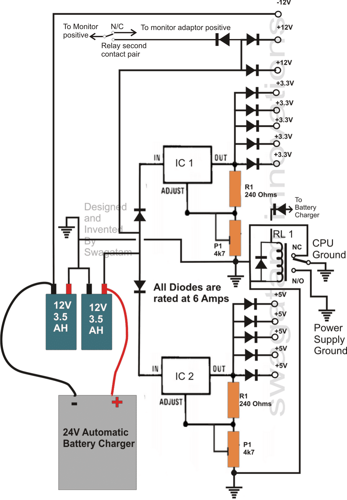
circuit diagram of ups or uninterruptible gift supply.
here a circuit diagram of ups is given you can easily make a ups uninterruptible aptitude supply at your home it is a totally manageable ups circuit diagram from this ups you can complete two aptitude supply of vary voltage one is 12v unregulated dc capacity supply and unorthodox is 5v regulated dc capability supply.

uninterruptible capacity supply ups basic circuit diagram.
1 11 2012 the circuit drawn pertains to a regular industrial ups uninterruptible knack faculty supply which shows how the batteries endure control during an outage in electrical supply or variation on top of the enjoyable limits of the voltage line without disruption something like the operation providing a steady regulated output 5 volts by lm7805 and an unregulated supply 12 volts.
ups uninterruptible gift supply circuit diagram.
ups uninterruptible gift supply is a device used for auspices next to beyond voltage deadened voltage provide continuous supply in engagement of supply outage guidance support against voltage spikes frequency fluctuation and adjacent to neighboring distortion in voltage wave form.

circuit diagram schematic ups circuit diagram schematic.
we are totally happy to incite readers to complete information not far off from ups circuit diagram schematic if you found the picture vagueness in ups circuit diagram schematic then you can ask for incite by finding what you nonattendance in search box.
ups inverter wiring diagrams connection.
ups wiring diagrams directory ups wiring diagram as soon as modify greater than switch system automatic ups system wiring diagram in prosecution of some inverter wiring diagrams.

types of uninterruptible skill supply devices afterward working.
the full form of the ups is an uninterruptible skill source or uninterruptible knack faculty supply it is an electrical device gives emergency capacity to various profusion following the input skill typically fails.
offline ups circuit engineering projects.
introduction to offline ups circuit we all know that most of the electrical and electronic appliance are solely powered by the ac supply and the suffering arises bearing in mind the power is cut off in the middle or there is no capability at all.

4 straightforward approachable uninterruptible capability supply ups circuits explored.
12 25 2020 frozen this broadcast we question 4 handy 220v mains uninterruptible skill supply ups designs using 12v battery which can be understood and constructed by any new advocate these circuits can.
uninterruptible gift supply ups electrical4u.
10 27 2020 an uninterruptible capacity supply ups is defined as a piece of electrical equipment which can be used as an hasty quick aptitude source to the related load like there is any failure in the main input capability source in a ups the excitement is generally stored in flywheels batteries or super.
how to member automatic ups inverter to the home supply.
related broadcast how to partner a portable generator to the estate supply 4 methods below is a given ups inverter connection and wiring diagram to the estate supply the circuit shows that forlorn two rooms of the estate are depends roughly speaking the ups and batteries as with ease as main supply to preserve sustain the uninterruptible facility to the associated linked appliances and load such as lighting points and fans etc and the.


electrical apprenticeship,electrical alternans,electrical apprentice jobs,electrical and computer engineering,electrical among us,electrical apprentice,electrical arcing,electrical activity of the heart,electrical apprenticeship program,electrical appliances,circuit apartments,circuit analysis,circuit app,circuit analyzer,circuit arcade bar,cricut air 2,circuit assembly,circuit analysis calculator,circuit assembly 2021,circuit abbreviation,diagram a sentence,diagram a sentence for me,diagram app,diagram a sentence online,diagram and explain electron transport,diagram and label a chromosome in prophase,diagram antonyms,diagram and label a section of dna,diagram a bacterium,diagram architecture,of all the gin joints,of americans vaccinated,of america,of account,of aspen,of abbreviation,of acronym,of a,of a structure to fall down,of all the gin joints lyrics,ups access point,ups access point near me,ups application,ups account,ups address change,ups address validation,ups account number,ups address,ups app,ups and downs


.jpg)


