A Comprehensive Guide to AC Motor Wiring Diagrams for Single-Phase Systems
wire diagram 1999 harley evo unadulterated wiring schemas.
10 16 2016 1999 evo wiring diagram wiring schematic diagram.
Understanding Single-Phase AC Motors
sdc35 36 user s manual single loop controller capacity supply.
no cp sp 1150e sdc35 36 single loop controller user s manual for installation configuration thank you for purchasing the sdc35 36 single loop controller this reference book contains recommendation for ensuring the precise exact use of the sdc35 36.controller reference book sdc36 relay capacity supply.
3 controller manual sdc36 set free release ebook download as pdf file pdf text file txt or retrieve book online for free.
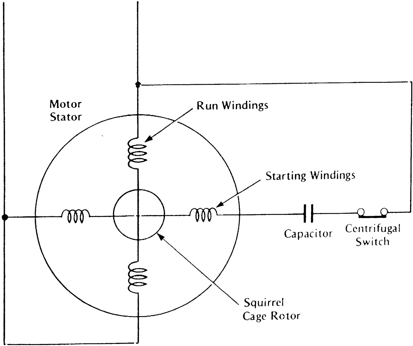
Components of an AC Motor Wiring Diagram (approx. 100 words):
ford fusion stereo wiring color diagram wiring diagram.
3 24 2019 it shows the components of the circuit as simplified forms and moreover then the facility and signal friends in in the middle of the tools any user assumes the entire risk as to the precision and use of this information.Step-by-Step Guide to AC Motor Wiring Diagrams :
- Identify the motor's main winding, start winding, capacitor, and centrifugal switch terminals by referring to the motor's specifications or the wiring diagram itself.
- Ensure the power supply is disconnected and the motor is safely isolated before proceeding.
- Connect one end of the power supply to the L1 terminal and the other end to the motor's common terminal (usually labeled L2 or T2).
- Connect the start winding to the start capacitor and the other side of the capacitor to the power supply's L2 terminal.
- Connect the centrifugal switch to the start winding and ensure it is in series with the start capacitor.
- Finally, connect the motor's frame or housing to the ground for safety purposes.

Understanding AC motor wiring diagrams for single-phase systems is crucial for correct installation and troubleshooting. By familiarizing yourself with the various components, symbols, and step-by-step procedures, you can confidently wire single-phase AC motors, ensuring their proper functioning and longevity in a wide range of applications.


Wiring Diagram Symbols and Terminology :
To comprehend an AC motor wiring diagram, it's crucial to understand the symbols and terminology commonly used. The diagram typically includes symbols for the main winding, start winding, capacitor, centrifugal switch, power supply, and ground. Additionally, it may feature labels for connection terminals such as L1, L2, and L3 (for line voltage), C (for capacitor), S (for start winding), and M (for main winding). Familiarizing yourself with these symbols and terms will make it easier to interpret and follow the wiring diagram accurately.