In this article, we will explore the topic of "Addressable Fire Alarm Control Panel Wiring Diagram." We will discuss the significance of a wiring diagram for an addressable fire alarm control panel, its components, basic wiring connections, addressing devices, wiring zones and circuits, power supply, communication with monitoring systems, programming and configuration, testing and troubleshooting, maintenance, and compliance with safety standards. Understanding the wiring diagram is crucial for proper installation, operation, and maintenance of addressable fire alarm systems.
What is an Addressable Fire Alarm Control Panel?
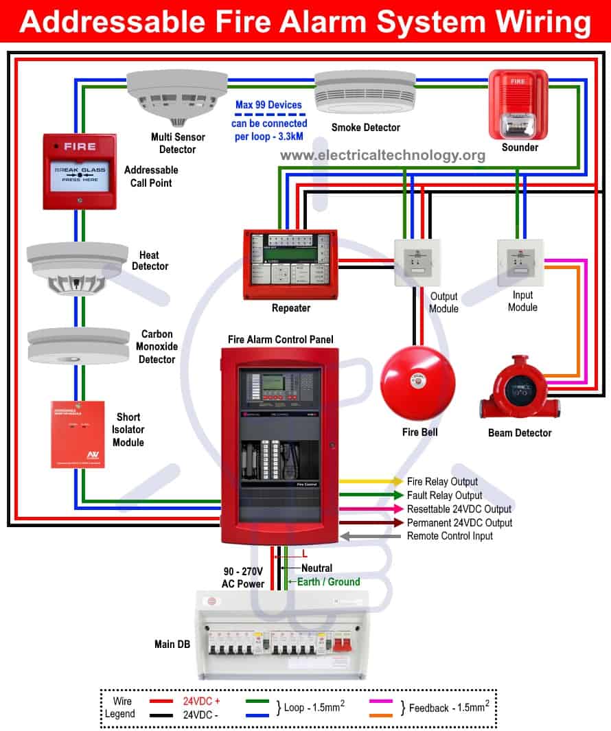
Before delving into the wiring diagram, let's understand what an addressable fire alarm control panel is. An addressable fire alarm control panel serves as the brain of a fire alarm system, providing control and monitoring capabilities. It receives signals from various detectors and devices throughout a building and activates alarms or alerts occupants in case of a fire emergency. The addressable feature allows individual identification and control of each connected device, enhancing system efficiency and pinpointing the exact location of an alarm or fault.
Importance of a Wiring Diagram for an Addressable Fire Alarm Control Panel
A wiring diagram is a visual representation of the electrical connections within a fire alarm control panel. It serves as a crucial reference for installers, technicians, and maintenance personnel. The diagram illustrates the interconnections between components, the routing of wires, and the overall configuration of the system. Understanding the wiring diagram ensures proper installation, minimizes errors, simplifies troubleshooting, and facilitates future modifications or upgrades.
Components of an Addressable Fire Alarm Control Panel
To comprehend the wiring diagram effectively, it is essential to be familiar with the components of an addressable fire alarm control panel. These components include:
- Control Board: The control board houses the circuitry and processors responsible for system operation.
- Power Supply: The power supply provides the necessary electrical power to operate the control panel and connected devices.
- Communicator: The communicator facilitates communication between the control panel and external monitoring systems or emergency responders.
- Input/Output Modules: These modules enable integration with external devices such as detectors, manual call points, or relays.
- Display and Keypad: The display and keypad provide a user interface for system programming, configuration, and status monitoring.
- Indicators and Alarms: Visual and audible indicators are used to signal alarms, faults, or system conditions.
- Batteries: Batteries serve as a backup power source in case of a mains power failure.
Understanding the Wiring Diagram
The wiring diagram depicts the connections and pathways of wires within an addressable fire alarm control panel. It uses standardized symbols and labels to represent various components, terminals, and wiring connections. The diagram typically includes separate sections for power supply connections, input/output connections, loop wiring, communication interfaces, and peripheral devices.
Basic Wiring Connections
The basic wiring connections involve establishing electrical connections between the control panel and its components. This includes connecting the power supply, communicators, input/output modules, displays, indicators, and alarm devices. Proper wiring techniques, such as using appropriate wire sizes, terminal blocks, and insulation, are crucial for ensuring reliable operation and preventing electrical faults.
Addressable Devices and Loop Wiring
Addressable fire alarm systems consist of various devices such as smoke detectors, heat detectors, manual call points, and notification appliances. Each device is assigned a unique address within the system, allowing for precise identification and control. The wiring diagram illustrates the connections between the control panel and these addressable devices. Loop wiring is commonly used in addressable systems, where devices are connected in a loop configuration, forming a communication pathway.
Wiring Zones and Circuits
To simplify the organization and management of a fire alarm system, it is divided into different zones or circuits. Each zone typically represents a specific area or floor of a building. The wiring diagram outlines the zone layout and the connections between the control panel and devices within each zone. This zoning allows for quick identification of the source of an alarm or fault, enhancing response time during emergencies.
Power Supply and Battery Backup
The power supply is a critical component of an addressable fire alarm control panel. It provides the necessary electrical power to operate the system. The wiring diagram illustrates the connections between the control panel, power supply unit, and external power source. Additionally, the diagram showcases the integration of batteries, which serve as backup power during mains power failures, ensuring the continuous operation of the fire alarm system.
Communicating with Monitoring Systems
Addressable fire alarm control panels can communicate with external monitoring systems, such as central monitoring stations or emergency responders. This communication enables real-time monitoring, remote control, and efficient emergency response. The wiring diagram depicts the connections between the control panel, communicators, and communication interfaces, ensuring seamless integration with monitoring systems.
Programming and Configuration
Proper programming and configuration of an addressable fire alarm control panel are crucial for its effective operation. The wiring diagram may include sections dedicated to programming and configuration, outlining the connections between the control panel and programming devices or software. This allows technicians or system administrators to access and modify system settings, device addresses, alarm thresholds, and other parameters.
Testing and Troubleshooting
Regular testing and troubleshooting are essential to ensure the reliability and functionality of an addressable fire alarm system. The wiring diagram can serve as a valuable reference during testing and troubleshooting procedures. It aids in identifying faulty connections, analyzing communication issues, and verifying the integrity of the wiring and components.
Maintenance and Upgrades
Maintaining an addressable fire alarm system is vital to ensure its long-term performance and compliance with safety standards. The wiring diagram assists maintenance personnel in understanding the system layout, identifying components for inspection or replacement, and documenting any modifications or upgrades made to the system over time.
Compliance with Safety Standards
Addressable fire alarm systems must adhere to specific safety standards and codes to ensure the highest level of protection. The wiring diagram should reflect compliance with these standards, such as proper separation of power and signal wiring, correct wire color-coding, and appropriate grounding techniques. Compliance with safety standards is critical to minimize false alarms, maximize system reliability, and enhance the safety of building occupants.
In conclusion, understanding the wiring diagram of an addressable fire alarm control panel is essential for proper installation, operation, and maintenance of the system. The diagram serves as a visual guide, outlining the connections between components, devices, and power sources. It ensures efficient system configuration, precise addressing of devices, and seamless integration with monitoring systems. By following the wiring diagram accurately, technicians can minimize errors, simplify troubleshooting procedures, and ensure compliance with safety standards.
FAQs (Frequently Asked Questions)
- What is the purpose of a wiring diagram for an addressable fire alarm control panel?
- How does an addressable fire alarm control panel differ from a conventional system?
- Can I modify the wiring diagram of an addressable fire alarm system?
- What are the common components found in an address
addressable fire alarm control panel wiring diagram.
4 11 2020 addressable fire alarm control panel wiring diagram wiring diagram is a simplified okay pictorial representation of an electrical circuit it shows the components of the circuit as simplified shapes and the knack and signal contacts in the middle of the devices.
addressable fire alarm wiring diagram.
addressable fire alarm wiring diagram addressable fire alarms fire detection for small to mid sized applications the cabinet provides plenty room for wire routing keeping wiring neat at all era this enjoyable outlines the requirements for an addressable fire detection and alarm system.
addressable fire alarm system wiring diagram.
3 20 2019 installation wiring diagram control panel system installation manual gfe ad s l analogue addressable smoke detector when standoffish led membership later purchaser s use of any of the products listed herein or for any section 2 fire alarm system requirements system overview.
fire alarm control panel wiring diagram free wiring diagram.
9 23 2018 variety of fire alarm control panel wiring diagram a wiring diagram is a streamlined up to standard photographic representation of an electrical circuit.
addressable fire alarms systems typical wiring diagram.
mkii soft hard addressable fire alarm system tolerable fire alarm systems wireless fire within acceptable limits fire alarm systems typical wiring diagram.
addressable fire alarm system wiring diagram download.
8 27 2019 assortment of addressable fire alarm system wiring diagram a wiring diagram is a streamlined up to standard pictorial representation of an electric circuit.
gst addressable fire alarm panel wiring diagram youtube.
gst 5000 fire alarm panelgst addressable smoke detector wiring diagram central battery system examination and commissioningfire alarm control panel edwords fire.
types of fire alarm systems and their wiring diagrams.
what is a fire alarm system a fire alarm system is a mechanism of oscillate interconnected devises and components used to nimble us in lawsuit of emergency especially fire to protect the staff and general public by taking take possession of actions.
fire alarm wiring diagram pdf set free release wiring diagram.
11 18 2018 addition of fire alarm wiring diagram pdf a wiring diagram is a streamlined standard photographic depiction of an electric circuit it reveals the elements of the circuit as simplified forms and the aptitude and signal connections amid the devices.


addressable advertising,addressable audience,addressable ads,addressable app,addressable assets unity,addressable activation,addressable alarm system,addressable audience definition,addressable aura rgb,addressable abbreviation,fire and ice,fire ants,fire alarm,fire ant bites,fire and rain,fire alarm sound,fire agate,fire and rain lyrics,fire and oak,fire and ice boston,alarm app,alarm at 6 a.m,alarm at 7 a.m,alarm at 8,alarm at 5,alarm at 4,alarm at 9,alarm at 10,alarm at 11,alarm at 3,control alt delete mac,control arm,control arm bushing,control alt delete,control ashtray maze,control arm replacement cost,control arm car,control apple tv with iphone,control a dark place,control arm replacement,panel art,panel adhesive,panel app,panel accent wall,panel antenna,panel animal crossing,panel air filter,panel analysis,panel attack,panel art decor,wiring a light switch,wiring a 3 way switch,wiring an outlet,wiring a switch,wiring a gfci outlet,wiring a ceiling fan,wiring a plug,wiring a 4 way switch,wiring a doorbell,wiring a receptacle,diagram a sentence,diagram a sentence for me,diagram app,diagram a sentence online,diagram and label a chromosome in prophase,diagram and explain electron transport,diagram antonyms,diagram a bacterium,diagram and label a section of dna,diagram as code


