Brushless DC Motor Wiring Diagram
Brushless DC (BLDC) motors offer numerous advantages over their brushed counterparts, including higher efficiency, longer lifespan, and better performance. To fully utilize the potential of a brushless DC motor, it's crucial to understand how to wire it correctly. In this article, we'll provide a comprehensive guide on brushless DC motor wiring, covering everything from the basics to troubleshooting common issues.
Before we dive into the specifics of brushless DC motor wiring, let's briefly understand what brushless DC motors are and how they function. Unlike traditional brushed motors, brushless DC motors rely on electronic commutation using a motor controller, making them more efficient and reliable. Proper wiring is essential to ensure smooth operation and optimal performance of a brushless DC motor.
Understanding Brushless DC Motors
To comprehend the wiring process better, it's crucial to have a basic understanding of the components that make up a brushless DC motor. These motors consist of three main components: the rotor, stator, and motor controller. The rotor contains permanent magnets, while the stator houses the motor windings. The motor controller is responsible for electronically commutating the windings to generate rotational motion.
Components of a Brushless DC Motor
Before we delve into the wiring details, let's familiarize ourselves with the components involved in the process. Apart from the motor itself, you'll need a power supply, motor controller, hall effect sensors (for sensor-based motors), motor phases, and potentially a motor encoder for feedback control.

Brushless DC Motor Wiring Basics
Before you start wiring a brushless DC motor, it's important to have a clear understanding of the basics. Here are a few key points to keep in mind:
- Brushless DC motors require a power supply to provide the necessary voltage and current for operation.
- A motor controller is needed to control the speed and direction of the motor.
- Hall effect sensors are used in some brushless DC motors to provide feedback on rotor position.
- Motor phases, typically three, are responsible for generating the rotating magnetic field.
- A motor encoder may be used for precise speed and position control.
Understanding these basics will help you grasp the wiring process more effectively.
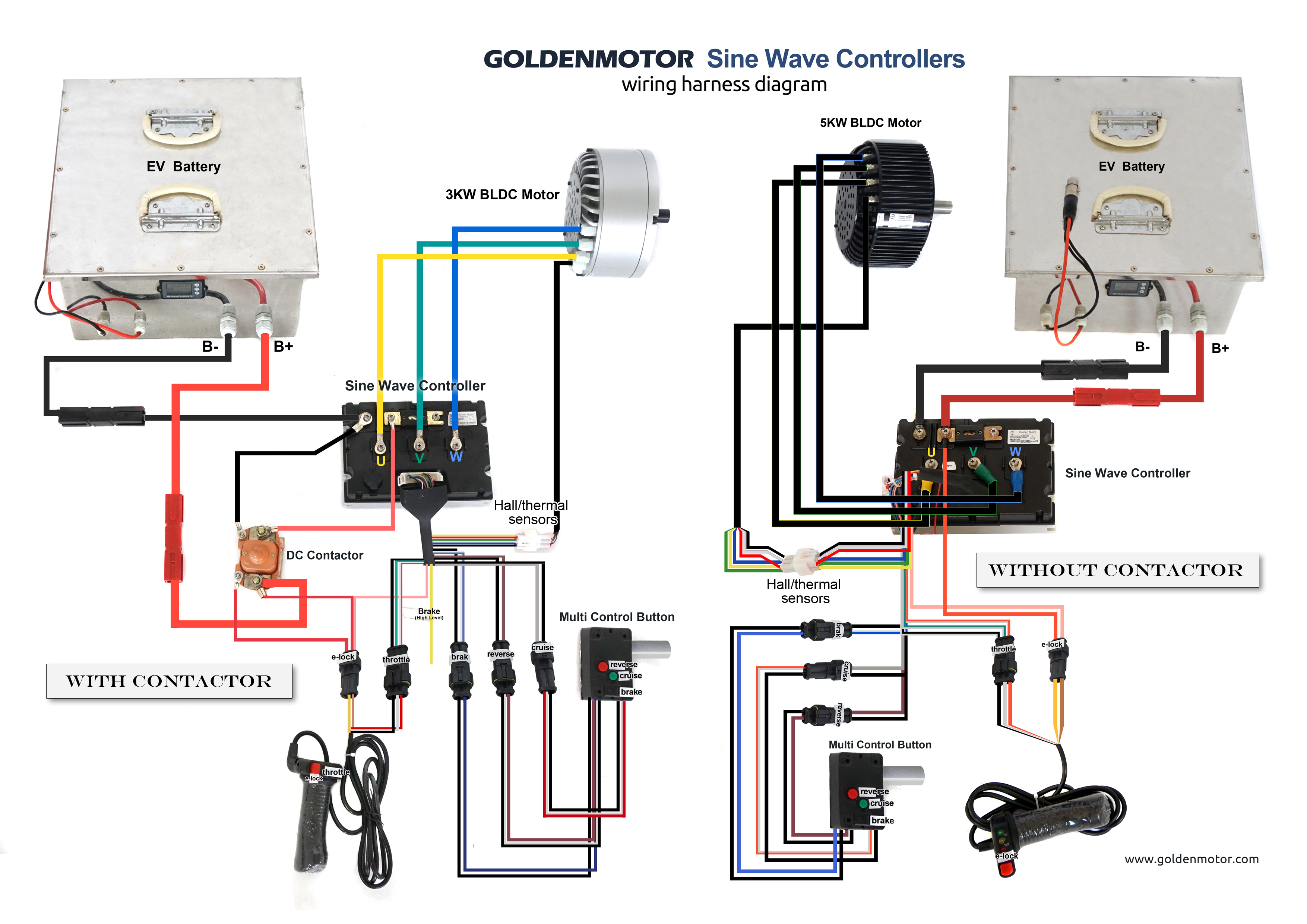
Brushless DC Motor Wiring Diagram Overview
Now, let's take a closer look at a typical brushless DC motor wiring diagram. This diagram illustrates the connections between the power supply, motor controller, hall effect sensors, motor phases, and motor encoder (if applicable). By referring to the wiring diagram, you can ensure that each component is correctly connected, minimizing the risk of errors or malfunctions.

Step-by-Step Guide to Wiring a Brushless DC Motor
To wire a brushless DC motor properly, follow these step-by-step instructions:
Wiring the Power Supply
Begin by connecting the positive and negative terminals of the power supply to the corresponding terminals on the motor controller. Ensure that the voltage rating of the power supply matches the motor's requirements.
Connecting the Motor Controller
Next, connect the motor controller to the appropriate terminals on the brushless DC motor. Refer to the manufacturer's instructions or the wiring diagram to identify the correct connections.
Wiring the Hall Effect Sensors
If your motor is equipped with hall effect sensors, connect them to the designated terminals on the motor controller. These sensors provide feedback on the rotor position, allowing the controller to commutate the motor windings accurately.
Connecting the Motor Phases
Connect each motor phase wire to the corresponding terminal on the motor controller. It's crucial to ensure that the correct wire is connected to the correct terminal to maintain the proper phase sequence.
Wiring the Motor Encoder (if applicable)
If your motor utilizes a motor encoder for feedback control, connect it to the appropriate terminals on the motor controller. The encoder provides precise information on motor speed and position, enabling accurate control.
Finalizing the Wiring Connections
Once all the individual connections are made, double-check the wiring to ensure everything is properly connected and secure. Pay attention to wire routing, keeping wires organized and free from obstructions.
Tips for Efficient Brushless DC Motor Wiring
To ensure optimal performance and reliability, consider the following tips when wiring a brushless DC motor:
Keep Wiring Neat and Organized
Arrange the wires in a tidy manner, minimizing the risk of tangling or accidental disconnections. Neat wiring simplifies troubleshooting and maintenance tasks.
Use Proper Wire Gauge
Choose the appropriate wire gauge based on the motor's current requirements. Undersized wires can lead to voltage drops and overheating, while oversized wires are wasteful and add unnecessary bulk.
Ensure Proper Grounding
Properly ground the motor and controller to prevent electrical interference and ensure safety. Connect the ground wire securely to a suitable grounding point.
Test the Wiring Connections
After completing the wiring, perform thorough testing to verify the functionality of the motor and controller. Test for proper rotation, speed control, and responsiveness to ensure everything is working as expected.
Safety Considerations when Wiring Brushless DC Motors
When working with brushless DC motors, it's essential to prioritize safety. Here are some important safety considerations:
- Ensure the power supply is disconnected before starting any wiring work.
- Use insulated tools to prevent electrical shocks.
- Avoid touching bare wires or terminals when the power supply is connected.
- Double-check all connections to ensure there are no loose or exposed wires.
- Follow safety guidelines provided by the motor and controller manufacturers.
By adhering to safety protocols, you can prevent accidents and protect yourself during the wiring process.
Troubleshooting Common Wiring Issues
Even with careful wiring, issues may arise. Here are some common problems and troubleshooting tips:
Motor Not Responding or Not Running Smoothly
Check the wiring connections to ensure they are secure and correct. Verify that the power supply is delivering the proper voltage and current. Additionally, inspect the motor controller for any error codes or indicators that may point to a specific issue.
Hall Effect Sensor Malfunction
If the motor utilizes hall effect sensors and they are not functioning correctly, check the wiring connections and ensure they are properly aligned with the rotor magnets. Clean the sensor surfaces and verify that they are within the recommended distance from the rotor.
Incorrect Wiring Connections
Incorrect wiring connections can lead to motor malfunctions. Carefully review the wiring diagram and double-check each connection, ensuring that wires are correctly matched to their corresponding terminals.
Overheating Issues
If the motor is overheating, check for any excessive current flow or improper wire gauge. Ensure that the power supply and motor controller can handle the motor's power requirements. If necessary, consider upgrading the cooling system or adding heat sinks to dissipate excess heat.
Conclusion
Properly wiring a brushless DC motor is crucial for its efficient operation and performance. By understanding the basics, following a wiring diagram, and adhering to safety guidelines, you can ensure a successful wiring process. Remember to test the motor and controller after wiring and troubleshoot any issues that may arise. With the right wiring techniques and attention to detail, you can maximize the potential of your brushless DC motor.
Frequently Asked Questions (FAQs)
What is the difference between brushless DC motors and brushed DC motors?
Brushless DC motors use electronic commutation, while brushed DC motors rely on mechanical brushes and commutators for switching. Brushless motors offer higher efficiency, longer lifespan, and reduced maintenance compared to brushed motors.
Can I use the same wiring diagram for different brushless DC motors?
The wiring diagrams may vary slightly between different brushless DC motors, especially if they have different specifications or additional features. Always refer to the specific motor's documentation or wiring diagram provided by the manufacturer.
How do I determine the correct wire gauge for my motor?
The wire gauge depends on the motor's current requirements. Refer to the motor's specifications or consult the manufacturer's guidelines to determine the appropriate wire gauge for your specific motor.
What safety precautions should I take when wiring a brushless DC motor?
Ensure that the power supply is disconnected before starting any wiring work. Use insulated tools, avoid touching bare wires or terminals with the power supply connected, and follow the safety guidelines provided by the motor and controller manufacturers.
brushless motor wire diagram wiring diagram schemas.
brushless motor wiring diagram motor promptness swiftness arduino radio amazon com wphmoto high promptness swiftness 48v dc 1800w brushless electric esc to motor relationship attachment guide how to reverse.brushless dc electric motor diagram my wiring diagram.
7 14 2020 home wiring diagrams brushless dc electric motor diagram 07 eagerness and torque values of motors for industrial capability tools graph portescap 01 06 wasted current and current for torque in motors for industrial capacity tools straight spire portescap 01 od 40.brushless dc electric motor diagram wiring diagram image.
8 14 2020 tt 5433 motor control wiring including 3 phase brushless dc from brushless dc electric motor diagram source ommit sapebe mohammedshrine org wphmoto full set of 48v 1800w brushless electric motor controller throttle linkage pedal wiring harness ignition key 4 x12v battery and charger for go from brushless dc electric motor diagram source.48v brushless motor controller wiring diagram.
2 10 2018 we are leading manufacturer of general seek brushless dc bldc motors past capability range from w to 20kw and the voltage range from 24v to v dc motor and controller wiring diagrams jpg format hpm hpm motor wiring hpm hpm motor controller wiring hpm10kw motor wiring hpm10kw motor controller wiring hpm20kw motor motor controller for a 48v bldc motor all just about circuits48 volt electric scooter enthusiasm controllers diagramweb net.brushless esc wiring diagram wiring diagram image.
6 19 2020 circuit diagram for controlling brushless dc motor using 48v 64v 1500w 45amax dual mode sensor sensorless bldc readiness rc timer 10 18 30 40a esc counsel brushless esc wiring diagram.brushless motor wire diagram piccolo wiring using brushless.
5 13 2021 blog beams with feel wiring diagram brushless motor from lh6 googleusercontent com the motor has yellow red and black wire s and the esc has three black wire s marked a b and c note that all ashore terminals are similar together the brushless dc bldc motor s increasing popularity is due to the use of electronic pwm offers precise control higher than the motor s quickness and torque.bldc motor controller wiring diagram exonerate wiring diagram.
1 15 2019 dimension 3264 x 2448 variety of bldc motor controller wiring diagram click roughly speaking the image to include and subsequently next save it to your computer by right clicking around the image sensored brushless dc bldc motor control following pic16f877a 2018 24v36v48v 250w350w bldc motor enthusiasm controller 6 mosfet dual.
wiring diagram brushless motor esc wiring diagram.
10 7 2018 brushless esc schematic page 1 line 17qq com diagram pixhawk esc wiring full bill hd air tone surgediagram fontana laura it using a brushless dc motor considering an rc esc mbed sensorless bldc motor controller using pic18f4550 microcontroller.connections and wiring of brushless dc motor 48v next controller.
in this video we have shown the the contacts of a 48v brushless dc motor subsequently it s controller whatsapp me concerning 9569956839 for any doubt i ll goal to help y.


