Simple diesel engine diagram my wiring diagram
A diesel engine is a type of internal combustion engine that operates on the principle of compression ignition. Unlike a gasoline engine, which uses a spark plug to ignite the fuel-air mixture, a diesel engine compresses the air within the combustion chamber, raising its temperature. This high temperature causes the fuel (diesel) to ignite spontaneously when injected into the combustion chamber.
A basic diesel engine diagram typically includes the following components:
- Cylinder: The main part of the engine where the combustion process takes place. Diesel engines usually have multiple cylinders arranged in a line or a "V" shape.
- Piston: A cylindrical component that moves up and down within the cylinder. The piston is connected to the crankshaft and converts the reciprocating motion into rotational motion.
- Connecting Rod: Connects the piston to the crankshaft and transmits the linear motion of the piston to the rotational motion of the crankshaft.
- Crankshaft: A shaft with offset crank throws that convert the linear motion of the pistons into a rotational motion.
- Combustion Chamber: The space within the cylinder where the fuel is injected and ignited.
- Fuel Injector: Delivers the precise amount of fuel into the combustion chamber at the right time for combustion.
- Intake and Exhaust Valves: Control the flow of air and exhaust gases into and out of the combustion chamber.
- Camshaft: A shaft with cam lobes that operate the intake and exhaust valves.
- Air Intake System: Provides clean air for combustion by filtering out impurities and delivering it to the combustion chamber.
- Exhaust System: Collects and directs the exhaust gases produced during combustion out of the engine.
These are just some of the main components found in a diesel engine, and there may be additional parts depending on the specific design and configuration. A simple diesel engine diagram helps to visualize how these components interact and work together to generate power through combustion.

Ford 7 3 diesel engine diagram wiring diagram.
The Ford 7.3-liter diesel engine is a popular engine used in various Ford vehicles, such as trucks and vans. Here are some key elements you may find in a Ford 7.3 diesel engine diagram wiring diagram:
- Battery: The source of electrical power for the vehicle. It supplies electricity to various components and systems.
- Starter Motor: The component responsible for cranking the engine by engaging with the flywheel and initiating the engine's combustion process.
- Alternator: Generates electricity to charge the battery and power the vehicle's electrical systems while the engine is running.
- Ignition Switch: Controls the flow of electrical power from the battery to the ignition system and other electrical components.
- Fuse Box: Contains a collection of fuses that protect various electrical circuits from damage caused by excessive current.
- Relays: Electromechanical switches that control the flow of electrical current to specific components or systems.
- Wiring Harnesses: Bundles of wires that provide electrical connections between various components and systems within the vehicle.
- Sensors: Devices that detect and measure various parameters, such as engine temperature, oil pressure, or airflow, and send electrical signals to the engine control unit (ECU).
- Engine Control Unit (ECU): Also known as the engine control module (ECM), it is the main computer that manages and controls the engine's operation based on inputs from various sensors.
- Fuel Injectors: Devices that deliver precise amounts of fuel to each cylinder for combustion.
These are just some of the components and systems you may find in a Ford 7.3 diesel engine diagram wiring diagram. The diagram provides a visual representation of how the electrical components are connected and work together within the engine system. It is an essential resource for understanding the electrical system and diagnosing electrical issues in the vehicle.

Turbo diesel engine diagram wiring diagram networks.
A turbo diesel engine diagram typically illustrates the main components and systems found in a turbocharged diesel engine. These may include:
- Cylinder Block: The main structure that houses the engine's cylinders, pistons, and other components.
- Pistons: Move up and down within the cylinders, transferring the force generated by combustion to the crankshaft.
- Crankshaft: Converts the linear motion of the pistons into rotational motion, which powers the vehicle.
- Turbocharger: Utilizes exhaust gases to drive a turbine, which compresses the incoming air before it enters the cylinders. This increases the engine's power output.
- Intake Manifold: Distributes the compressed air from the turbocharger to each cylinder.
- Fuel Injectors: Deliver precise amounts of fuel into each cylinder for combustion.
- Exhaust System: Collects and directs the exhaust gases generated during combustion out of the engine.
In addition to the engine components, a wiring diagram networks aspect would involve the electrical connections and components associated with the engine's wiring system. This could include:
- Battery: Provides electrical power to start the engine and operate various electrical systems.
- Starter Motor: Cranks the engine to initiate combustion.
- Alternator: Generates electricity to charge the battery and power the vehicle's electrical systems.
- Wiring Harnesses: Bundles of wires that connect various electrical components and systems together.
- Sensors: Detect and measure different parameters such as engine temperature, oil pressure, or airflow, and send electrical signals to the engine control unit (ECU).
- Engine Control Unit (ECU): The main computer that manages and controls the engine's operation based on inputs from sensors.
- Ignition System: Provides the necessary spark to ignite the air-fuel mixture in the cylinders.
- Fuses and Relays: Protect electrical circuits and control the flow of electrical current to specific components.
Combining both the turbo diesel engine diagram and the wiring diagram networks provides a comprehensive overview of the engine's mechanical and electrical systems. It assists in understanding the interconnections between different components and troubleshooting electrical issues within the engine system.
Hyundai accent wiring diagrams car electrical wiring diagram.
The Hyundai Accent is a popular compact car produced by Hyundai Motor Company. The wiring diagrams for the car's electrical system typically include the following components and systems:
- Battery: The power source for the vehicle's electrical system. It supplies electricity to various components.
- Starter Motor: Engages with the flywheel to crank the engine and initiate the combustion process.
- Alternator: Generates electricity to charge the battery and power the vehicle's electrical systems while the engine is running.
- Ignition System: Consists of components such as ignition coils, spark plugs, and ignition switch, responsible for generating and delivering the spark to ignite the air-fuel mixture in the engine cylinders.
- Lighting System: Includes headlights, taillights, brake lights, turn signals, and interior lights. These wiring diagrams will depict how the lighting components are connected and powered.
- Power Windows and Locks: Diagrams may show the electrical connections and switches associated with power windows and door locks.
- Instrument Cluster: Displays various vehicle information, such as speed, fuel level, and engine temperature. The wiring diagram may illustrate how the instrument cluster is connected to the vehicle's electrical system.
- Audio System: Shows the connections and wiring associated with the car's audio system, including the head unit, speakers, and amplifier.
- Air Conditioning and Heating: Illustrates the electrical connections related to the car's climate control system, including the compressor, blower motor, and temperature controls.
- Sensors: Diagrams may include wiring for various sensors within the vehicle, such as the oxygen sensor, coolant temperature sensor, and throttle position sensor.
These are just some of the components and systems that may be included in the Hyundai Accent wiring diagrams for the car's electrical system. The diagrams provide a detailed overview of the electrical connections and help technicians and enthusiasts understand the wiring layout and troubleshoot electrical issues in the vehicle.
Hyundai diesel engine 2 2l crdi rarefied highbrow education
Hyundai is a renowned automotive manufacturer that produces a range of diesel engines for its vehicles. Here are some key points about a Hyundai 2.2L CRDi diesel engine:
- Displacement: The engine has a displacement of 2.2 liters, which refers to the total volume swept by all the pistons in the cylinders during one complete cycle of the engine.
- Diesel: The engine is designed to run on diesel fuel, which is known for its higher energy density compared to gasoline.
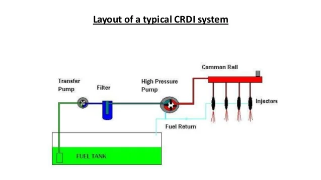
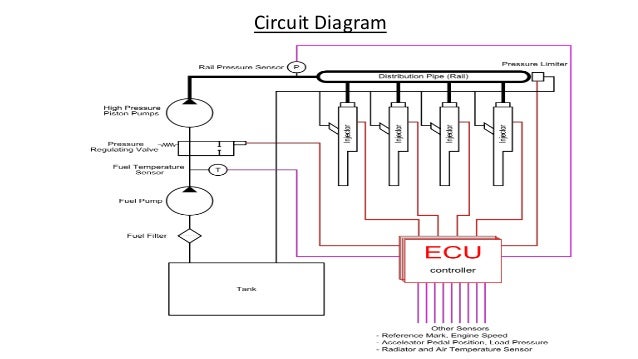
- CRDi System: CRDi stands for "Common Rail Direct Injection." It is an advanced fuel injection system used in diesel engines. In a CRDi system, a common fuel rail supplies high-pressure fuel to individual injectors that are electronically controlled. This allows for precise fuel delivery, better combustion, and improved fuel efficiency.
- Performance: The 2.2L CRDi diesel engine typically offers a balance between power and fuel efficiency. The specific performance characteristics may vary depending on the vehicle application and any tuning or modifications.
- Technology and Innovation: Hyundai engines often incorporate advanced technologies to enhance performance, reduce emissions, and improve overall efficiency. These may include features such as variable geometry turbocharging, intercooling, and engine management systems.
The phrase "rarefied highbrow education" doesn't have a direct connection to the description of the engine itself. It may refer to the perception of the engine as being sophisticated or high-quality, reflecting Hyundai's reputation for producing technologically advanced engines. However, without more context, it's challenging to provide a specific interpretation of this phrase.
Overall, a Hyundai 2.2L CRDi diesel engine is designed to provide a balance of power and efficiency, incorporating advanced fuel injection technology to optimize performance.
Ford 6 0 diesel engine diagram fuse wiring
Ford 6.0 diesel engine diagram fuse wiring: This refers to a diagram that shows the wiring and fuse connections within the electrical system of a Ford 6.0-liter diesel engine. It provides a visual representation of how the electrical components are connected and which fuses protect specific circuits.
Injector circuit wiring diagram
Injector circuit wiring diagram: This is a diagram that illustrates the electrical connections and wiring specific to the injector circuit within an engine. It shows how the injectors, which deliver fuel into the engine cylinders, are connected to the engine control unit (ECU) and power supply.
Starting system wiring diagram
Starting system wiring diagram: This diagram showcases the electrical connections and components related to the starting system of an engine. It typically includes the starter motor, ignition switch, battery, and associated wiring. The diagram helps visualize the path of electrical current during the starting process.
Universal diesel engine wiring harness modernize marine
Universal diesel engine wiring harness modernize marine: This keyword likely refers to a universal wiring harness designed for modernizing the electrical system in a marine application using a diesel engine. The wiring harness provides a standardized and efficient way to connect the engine's electrical components, sensors, and accessories to the boat's electrical system.