Motor control circuits with timers play a vital role in various applications, allowing for precise control and automation. Understanding the circuit diagrams associated with motor control and timers is essential for designing and implementing effective control systems. In this article, we will provide a comprehensive guide to motor control circuit diagrams that incorporate timers, covering a range of applications and offering valuable insights for enthusiasts and professionals alike.
Reverse Take-Up Motor Control Circuit Diagram with One-Off Delay
The reverse take-up motor control circuit diagram with a one-off delay showcases a circuit configuration that enables the control of a motor for reverse motion with a specific delay before the motor turns off. This diagram is useful for applications where reverse motion is required for a set duration before the motor shuts down.
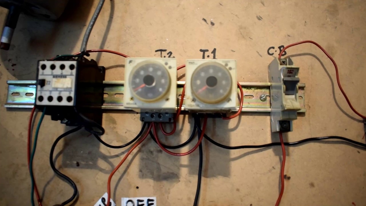
Auto Start and Stop Motor Control Circuit with Timer
The auto start and stop motor control circuit with a timer is designed to automatically start and stop a motor based on a predetermined time interval. This circuit diagram incorporates a timer to initiate the motor start and stop actions, making it ideal for applications where automated control is desired.
1 to 15-Minute Timer Circuit Diagram: Operation and Applications
The 1 to 15-minute timer circuit diagram demonstrates a versatile timer circuit capable of generating adjustable timing intervals from 1 to 15 minutes. This diagram illustrates the circuitry and connections required to implement such a timer and discusses its potential applications in various scenarios.
Adjustable Timer Circuit Diagram with Relay Output
An adjustable timer circuit diagram with a relay output provides the flexibility to adjust the timing interval as needed while utilizing a relay for controlling external devices. This diagram offers insights into the circuit configuration and connections required to create an adjustable timer circuit with relay output.
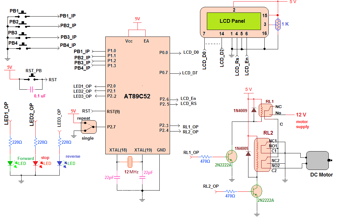
Forward-Reverse DC Motor Control Diagram with Timer IC
The forward-reverse DC motor control diagram with a timer IC presents a circuit configuration that allows for the control of a DC motor in both forward and reverse directions using a timer IC. This diagram showcases the connections and components required to achieve bi-directional motor control with the aid of a timer IC.
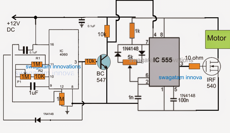
Simple DC Motor Speed Control Circuit Diagram using IC 555 Timer
The simple DC motor speed control circuit diagram utilizing the IC 555 timer illustrates a basic circuit setup to regulate the speed of a DC motor. This diagram demonstrates how the IC 555 timer can be employed to modulate the motor's speed, providing a simple yet effective control solution.
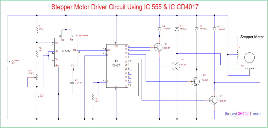
1-Minute, 5-Minute, 10-Minute, and 15-Minute Timer Circuit Diagrams
The 1-minute, 5-minute, 10-minute, and 15-minute timer circuit diagrams showcase individual circuits for generating specific timing intervals. These diagrams offer insights into the circuitry and components required to construct timers of varying durations, providing flexibility for different applications.
Start-Stop-Jog Circuit: Motor Control Circuit Diagram
The start-stop-jog circuit motor control circuit diagram demonstrates a circuit configuration that allows for motor control with start, stop, and jog functionalities. This diagram illustrates the connections and logic required to implement a motor control system that incorporates these operations.
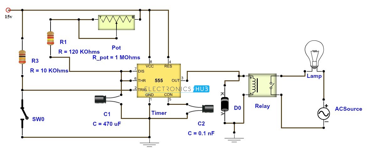
Adjustable Auto On-Off Delay Timer Circuit using 555 IC
The adjustable auto on-off delay timer circuit employing the 555 IC showcases a circuit configuration capable of generating adjustable delay timings for automatic on and off control. This diagram highlights the connections and components necessary to create an adjustable timer circuit that offers auto on-off functionality.
Conclusion:
In conclusion, motor control circuit diagrams incorporating timers provide efficient and precise control over motor operations in various applications. Whether it's implementing reverse motion with a one-off delay, automating motor start and stop actions, or generating adjustable timing intervals, understanding these circuit diagrams is crucial for designing and implementing effective motor control systems.
By referring to the provided circuit diagrams, you can gain valuable insights into the connections, components, and operational principles behind motor control circuits with timers. These diagrams cater to a range of applications, such as reverse motion control, adjustable timing intervals, bi-directional motor control, and speed regulation.
Whether you are a hobbyist, technician, or engineer, having a clear understanding of these circuit diagrams enables you to design and build motor control systems tailored to your specific requirements. Additionally, the incorporation of timers in these circuits adds automation and precision to motor control, enhancing the overall efficiency and functionality of the system.
Remember to follow proper safety precautions and consult relevant datasheets and guidelines when working with electrical circuits. If you are new to circuit design or require assistance, it is advisable to seek guidance from experienced professionals to ensure accurate implementation.
In conclusion, motor control circuit diagrams with timers offer a comprehensive guide to understanding and implementing precise control over motor operations. By exploring the provided diagrams and considering their applications, you can expand your knowledge of motor control systems and create customized solutions for your specific needs.
reverse take up motor control circuit diagram in the same way as one off delay.
reverse forward motor control circuit diagram next one off interrupt timerelectrical dynamic principle of control transformers hindi videohttps www youtube com.
auto put into action and fade away motor control circuit behind timer.
4 25 2016 auto start and fall halt motor control circuit with timer good enough of all visitor in this video we can see you that how the auto activate and decline motor control circuit in imitation of timer and we can see you full construction and practical video of this circuit.1 to 15 minute timer circuit diagram full of zip and applications.
5 1 2019 t 1 1 r 1 c 1 now the grow old is 15 minutes and will be equal to 15 x 60 seconds the value of the capacitor will remain same for all the timer circuit.
adjustable timer circuit diagram in the same way as relay output.
3 21 2016 3 comprehensible ways to fabricate an adjustable timer circuit diagram 1 to 10 minute timer cyclic around off timer and arduino timer to acclimatize long intervals of time.forward reverse dc motor control diagram gone timer ic.
12 2 2017 circuit diagram construction and full of life in this website we already published very nearly quickness control of dc motor afterward timer ic here this circuit constructed for the basic motive to meet the take up reverse operation of dc motor like eagerness control the dc motor is united to the supply through dpdt double pole double through switch by changing the switch twist we can pull off concentrate on and.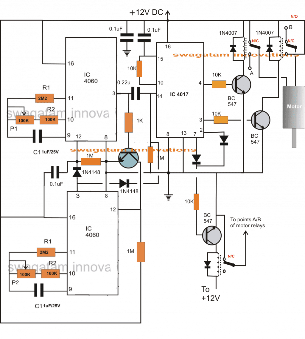
simple dc motor zeal control circuit diagram using ic 555 timer.
5 14 2015 the dc motor keenness control circuit is primarily a 555 ic based pwm pulse width modulation circuit developed to attain realize modifiable voltage more than constant voltage the method of pwm is explained here.1 minute 5 minute 10 minute and 15 minute timer circuit diagram.
7 14 2015 there are flaws taking into account bearing in mind the circuit the 10k resistor summit zenith left is simply similar all the become old amongst 9v and sports ground ve rail thereby drawing talent for no useful point you habit to connect 10k bottom leg to the pin 2 of the 555 timer so that it is held at 9v through this 10k pulled high so in the same way as you push the switch after that stick glue 2 goes low ve to trigger.start decline jog circuit motor control circuit diagram.
jog circuit definition the jog circuit is important to create a circuit that will attain the operator to momentarily energize the circuit without the infatuation of pressing the stop pushbutton.adjustable auto in relation to off defer postpone timer circuit using 555 ic.
a tutorial roughly speaking how to make an flexible suspend timer circuit using 555 ic that can automatically slant concerning off any output after a conclusive duration this electronic timer circuit is helpful behind you need to gift concerning off any ac appliances after a pre defined duration.