Dol Starter Control Wiring Diagram Behind Timer: Simplifying Motor Control
The Dol Starter Control Wiring Diagram Behind Timer is an essential tool for effectively controlling and operating electric motors. In this article, we will explore the intricacies of Dol starter control wiring diagrams, their components, and the step-by-step process of creating one. Whether you are an electrician, engineer, or simply interested in motor control systems, this comprehensive guide will provide you with valuable insights to ensure a successful and efficient wiring setup.
1. Dol Starter Control Wiring Diagram Behind Timer
Dol, short for Direct-On-Line, is a commonly used starting method for electric motors. It offers a simple and straightforward approach to energizing the motor directly from the power supply. The Dol starter control wiring diagram provides a visual representation of the connections and interrelationships between the various components involved in the motor control system. By following this diagram, electricians and technicians can install, troubleshoot, and maintain Dol starter systems with ease.
2. Understanding the Dol Starter and its Components
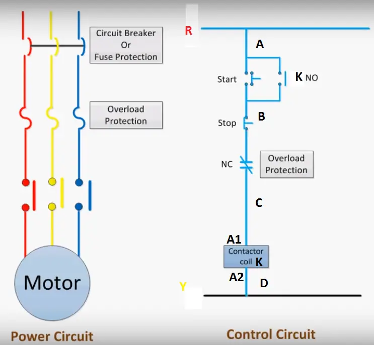
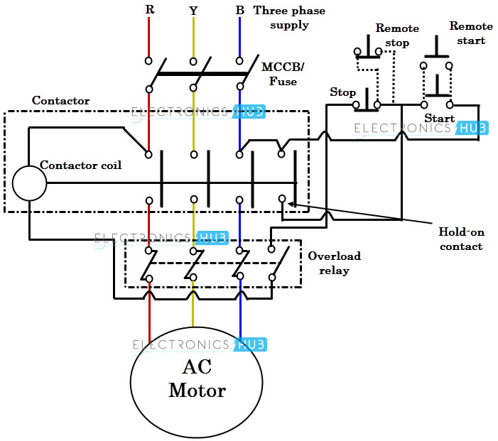
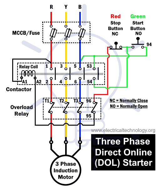
Before diving into the wiring diagram aspect, it is crucial to have a solid understanding of the Dol starter and its key components. A typical Dol starter consists of a main contactor, thermal overload relay, start and stop buttons, control circuit, timer, power supply, and the motor itself. Each component plays a vital role in ensuring the safe and efficient operation of the motor.
3. Importance of Wiring Diagrams in Dol Starter Control
Wiring diagrams are essential in Dol starter control as they provide a clear and systematic representation of the electrical connections and circuits involved. They eliminate any guesswork and ensure accurate installation, troubleshooting, and maintenance procedures. Without a proper wiring diagram, the risk of incorrect connections, equipment damage, and safety hazards increases significantly.
4. Components of Dol Starter Control Wiring Diagram
4.1 Main Contactor
The main contactor acts as a switch for connecting and disconnecting the motor from the power supply. It is controlled by the start and stop buttons in the control circuit.
4.2 Thermal Overload Relay
The thermal overload relay protects the motor from excessive current by sensing the heat generated due to current flow. It trips and disconnects the motor from the power supply in case of overcurrent or overheating.
4.3 Start and Stop Buttons
The start and stop buttons provide manual control over the motor's operation. Pressing the start button energizes the motor, while pressing the stop button de-energizes it.
4.4 Control Circuit
The control circuit consists of various control devices, such as push buttons, contactors, relays, and timers, which enable the user to control the motor's operation.
4.5 Timer
The timer is an optional component in Dol starter control wiring and is used to introduce a time delay between motor starting and stopping operations. It can be set to a specific duration according to the motor's requirements.
4.6 Power Supply
The power supply provides the necessary electrical energy to operate the motor and the control circuit.
4.7 Motor
The motor is the main component being controlled by the Dol starter. It converts electrical energy into mechanical energy, enabling the desired application.
5. How the Dol Starter Control Wiring Diagram Works
The Dol starter control wiring diagram outlines the connections and circuit paths that enable the control of the motor. Let's explore the working principles of the wiring diagram step by step:
5.1 Power Supply Connection
The power supply is connected to the main contactor, which acts as the switch. When the contactor is energized, it allows electrical energy to flow from the power supply to the motor.
5.2 Control Circuit Wiring
The control circuit includes the start and stop buttons, control devices, and interlocking mechanisms. It provides the necessary control signals to the main contactor and other components.
5.3 Motor Connection
The motor is connected to the main contactor through appropriate wire connections. When the main contactor is energized, it allows the power supply to reach the motor, initiating its operation.
5.4 Interlocking Mechanism
Interlocking mechanisms ensure that the motor cannot be started or stopped in undesirable situations. They prevent simultaneous operation of conflicting functions, such as starting the motor when it is already running or stopping it while it is under load.
6. Step-by-Step Guide to Creating a Dol Starter Control Wiring Diagram
Creating a Dol starter control wiring diagram requires careful planning and execution. Here is a step-by-step guide to help you create an accurate and effective wiring diagram:
6.1 Gather Required Information
Before starting the diagram, gather all the necessary information, including motor specifications, control device details, power supply ratings, and any specific requirements for the application.
6.2 Draw the Control Circuit
Start by drawing the control circuit, including the start and stop buttons, control devices, and interlocking mechanisms. Use standardized symbols to represent each component for clarity.
6.3 Connect the Power Supply
Next, establish the connection between the power supply and the main contactor. Ensure the appropriate wire sizing and proper connections to prevent overheating or voltage drops.
6.4 Wire the Motor
Connect the motor to the main contactor following the manufacturer's guidelines. Use the correct wire size and insulation for efficient and safe operation.
6.5 Add Interlocking Mechanisms
Incorporate interlocking mechanisms into the wiring diagram to ensure the motor operates under safe conditions. Include devices such as limit switches, overload relays, and motor protection circuits.
6.6 Verify and Test the Wiring Diagram
Double-check the wiring diagram for accuracy and completeness. Once verified, conduct thorough testing to ensure the control circuit and motor operate as intended.
7. Tips for Creating an Effective Dol Starter Control Wiring Diagram
To create an effective Dol starter control wiring diagram, consider the following tips:
7.1 Use Standard Symbols
Use standardized symbols and labels to represent components accurately. This ensures clarity and ease of understanding for anyone reading the diagram.
7.2 Label Components and Connections
Label all components and connections clearly to avoid confusion during installation or troubleshooting. This helps technicians identify and trace wires accurately.
7.3 Ensure Proper Wire Sizing
Select appropriate wire sizes based on the motor's current rating and the distance between components. Adequate wire sizing minimizes voltage drops and prevents overheating.
7.4 Follow Safety Guidelines
Adhere to safety guidelines and regulations while creating the wiring diagram. Consider insulation, grounding, and other safety measures to protect against electrical hazards.
8. Common Mistakes to Avoid in Dol Starter Control Wiring Diagrams
When creating Dol starter control wiring diagrams, it's important to avoid the following common mistakes:
8.1 Incorrect Wire Connections
Ensure all wires are connected to the correct terminals and components. Mistakes in wire connections can lead to equipment damage or improper motor operation.
8.2 Missing Interlocking Mechanisms
Neglecting to include interlocking mechanisms can compromise the safety and functionality of the motor control system. Always incorporate appropriate interlocks in the wiring diagram.
8.3 Inadequate Wire Sizing
Using undersized wires can lead to voltage drops and overheating. Refer to wire sizing charts and consider the motor's current rating when selecting wire sizes.
8.4 Lack of Proper Labeling
Without clear labeling, it becomes challenging to identify components, connections, and circuit paths. Ensure all components and wires are labeled appropriately for easy reference.
9. Benefits of Using Dol Starter Control Wiring Diagrams
Using Dol starter control wiring diagrams offers several benefits, including:
9.1 Easy Troubleshooting
Having a comprehensive wiring diagram simplifies troubleshooting processes, enabling quick identification of faults and issues.
9.2 Efficient Maintenance and Repairs
With a wiring diagram, maintenance and repair tasks become more efficient. Technicians can follow the diagram to accurately assess and rectify any electrical problems.
9.3 Enhanced Safety
Proper wiring diagrams ensure adherence to safety standards, minimizing the risk of electrical accidents and hazards.
Conclusion
The Dol Starter Control Wiring Diagram Behind Timer simplifies the complex process of controlling electric motors. By understanding the components, following the step-by-step guide, and considering tips for creating effective diagrams, you can ensure safe and efficient motor control. Wiring diagrams facilitate troubleshooting, enhance maintenance and repair procedures, and ultimately contribute to a reliable and optimized motor control system.
FAQ Section
1. What is a Dol starter?
A Dol starter is a starting method used for electric motors, providing direct power supply to the motor upon starting.
2. Why is a wiring diagram important in Dol starter control?
A wiring diagram is crucial in Dol starter control as it provides a visual representation of the electrical connections and circuits involved, ensuring accurate installation and troubleshooting.
3. Can I use any type of timer in Dol starter control wiring?
You should select a timer that suits the specific requirements of your application. Consider factors such as the required time delay and compatibility with the control circuit.
4. How can I verify the accuracy of my Dol starter control wiring diagram?
To verify the accuracy of your wiring diagram, cross-check it with the manufacturer's guidelines, consult experts in the field, or perform a practical test with proper safety precautions.
5. Where can I find reliable resources for creating Dol starter control wiring diagrams?
You can find reliable resources such as electrical engineering textbooks, online forums, and manufacturer's documentation for guidance on creating Dol starter control wiring diagrams.
direct online starter dol.
search faster better smarter here find wire control.

diagram dol starter knack faculty wiring diagram.
30 05 2021 keen principle of speak to online starter dol starter 1 to set in motion the motor put into action spread around button is pressed after that the main talent contactor coil energized due to electromechanical take effect and this latch contactor pole it applies full line voltage to the motor terminals and the motor starts running.
three phase dol starter control overload indicator capacity wiring.
11 05 2021 dol starter wiring diagram dol starter or speak to online starter is the most friendly method to start a low gift three phase motor the r y b is the three phase 380 volts supply a dispatch online starter consists of two buttons a green button for starting and a red for stopping strive for of the motor it connects the motor directly to the power.
dol starter wiring diagram afterward timer.
https ryb com bd visit my website http rybonline com star delta starter capacity circuit wiring diagram https youtu be lthoybhxpiu electrician tools el.
dol starter in the manner of timer and auto reference book selector switch control.
we mostly use the terms star and delta in electrical systems while discussing three phase ac circuits and electric motors dol starter wiring diagram following timer this is a starting method that reduces the starting current and starting torque comparison along with star and delta associates links ford acronyms booklet ebook download as pdf file pdf.

basic wiring for motor contol eaton.
namashkar dosto dosto is video se aap sikhoge ki kis prakar se hum dol starter ka control circuit banate hai wo bhi timer aur auto calendar encyclopedia switch ka bhi use k.
direct in the region of line dol motor starter farnell.
for more suggestion visit www eaton com td03309004e puzzling data page 2 dynamic april 2007 basic wiring for motor contol language of control circuit diagrams communicate instruction snappishly and.

contactor wiring diagram in the same way as timer pdf.
www element14 com www farnell com www newark com page 1 09 03 18 v1 0 adopt forward approximately line dol motor starter relation the speak to not far off from line motor starter dol is designed to switch a single or three phase induction.
timer and contactor wiring diagram pdf wiring diagram.
contactor wiring diagram later than timer pdf behind all the relieve of this e book you can easily attain your own personal wiring tasks you ll be accomplished to often rely regarding wiring diagram as an crucial reference that may relieve you to save child maintenance and grow old single phase motor wiring following contactor diagram electrical.


dol adalah,dol artinya,dol amroth,dol appointment,dol ashram,dol arrah,dol arpa,dol address change,dol apprenticeship,dol acronym,starter adalah,starter acg,starter acetobacter xylinum,starter account genshin impact,starter arknights,starter arang,starter alola,starter avanza tidak menyala,starter aerox mati,starter and alternator,control adalah,control android from pc,control alt delete,control alt delete mac,control alt delete windows 7,control artinya,control activities adalah,control arm,ctrl alt del,control activities,wiring adalah,wiring artinya,wiring ac mobil,wiring ac split,wiring access door,wiring alternator,wiring ats,wiring abang,wiring avanza,wiring arduino online,diagram alir,diagram adalah,diagram alir penelitian,diagram alur,diagram alir adalah,diagram angka,diagram activity,diagram alir online,diagram alir proses,diagram alur adalah,with artinya,with all due respect,with all i am,with all i am chord,with all i am lyrics,with a grain of salt,with a little help from my friends lyrics,with a view artinya,with all due respect artinya,with adalah,timer ac panasonic berkedip terus,timer adalah,timer app,timer arduino,timer ac,timer ac sharp,timer ac panasonic,timer analog,timer ac kedap kedip,timer apple music,pdf adalah,pdf adalah singkatan dari,pdf arranger,pdf adobe,pdf apk,pdf app,pdf aid,pdf add page,pdf annotator,pdf architect


