Importance of a Starter Wiring Diagram
Components of a Starter Wiring Diagram
- Battery: The battery supplies electrical power to the starter system. It provides the necessary energy to turn the engine.
- Starter Motor: The starter motor is responsible for physically cranking the engine when the ignition key is turned. It converts electrical energy into mechanical energy.
- Ignition Switch: The ignition switch is a crucial component that activates the starter system. It connects the battery to the starter motor and controls the flow of electricity.
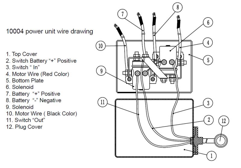
- Solenoid: The solenoid is an electromagnetic switch that connects and disconnects the high-current battery power to the starter motor. It acts as a bridge between the ignition switch and the starter motor.
- Starter Relay: In some vehicles, a starter relay is used to control the flow of current from the battery to the starter motor. It acts as a switch, allowing a small amount of current from the ignition switch to control a larger current flow from the battery to the starter motor.
- Fusible Links: Fusible links are designed to protect the electrical system from overloads. They are special wires that are slightly thinner than the regular wiring. If a short circuit or overload occurs, the fusible link will melt, breaking the circuit and preventing damage to the rest of the wiring.
Understanding the Wiring Diagram Symbols
Types of Starter Wiring Diagrams
- Conventional Wiring Diagram: This type of wiring diagram represents a traditional starter system with a direct connection between the ignition switch, solenoid, starter motor, and battery.
- Remote Starter Wiring Diagram: A remote starter wiring diagram includes additional components like a remote start module and an antenna. This diagram illustrates how the remote start system integrates with the existing starter wiring.
- Push Button Starter Wiring Diagram: In vehicles equipped with a push button start, this wiring diagram showcases the connections between the push button, ignition switch, starter motor, and other related components.
Steps to Read a Starter Wiring Diagram
- Identify the Components: Familiarize yourself with the different components mentioned in the wiring diagram and locate their positions within the vehicle.
- Study the Diagram Key: Understand the symbols and abbreviations used in the diagram key. It provides essential information about the representation of various components and connections.
- Follow the Wiring Paths: Trace the lines in the diagram to understand the flow of electrical current. Pay attention to the color-coded lines, as they indicate the specific wires used for different connections.
Common Issues with Starter Wiring
- Loose or Corroded Connections: Loose or corroded connections can disrupt the flow of electrical current, resulting in intermittent or no starting. Regular inspection and maintenance of the connections are essential to prevent such issues.
- Faulty Ignition Switch: A faulty ignition switch can prevent the flow of electrical current to the starter motor, rendering the starter system ineffective. Troubleshooting the ignition switch is crucial when diagnosing starting problems.
- Bad Starter Motor: A worn-out or malfunctioning starter motor may fail to crank the engine consistently. It can be identified through a series of diagnostic tests and should be replaced if necessary.
- Wiring Short Circuit: Short circuits occur when a wire's insulation wears out or gets damaged, causing the wire to come into contact with other wires or metal components. Short circuits can result in blown fuses, melted wires, or even electrical fires.
Troubleshooting Starter Wiring Problems
- Checking Battery Voltage: Use a multimeter to measure the voltage of the battery. Low voltage can indicate a weak or discharged battery, which may require charging or replacement.
- Testing Ignition Switch: Check the continuity of the ignition switch using a multimeter. If it fails to provide a continuous circuit, it may need to be replaced.
- Inspecting Starter Motor Connections: Inspect the connections between the starter motor and the solenoid for loose or corroded terminals. Clean and tighten the connections if necessary.
- Using a Multimeter for Continuity Testing: A multimeter can help you test the continuity of wires and ensure proper connections throughout the starter system.
Safety Precautions while Working with Starter Wiring
- Disconnecting the Battery: Before working on any electrical components, disconnect the vehicle's battery to prevent accidental electrical shocks.
- Using Proper Tools and Techniques: Always use appropriate tools and follow recommended techniques when working with electrical connections. This includes using insulated tools, avoiding shortcuts, and securing wiring harnesses properly.
- Avoiding Short Circuits: Take precautions to prevent accidental short circuits by ensuring that wires are properly insulated, protected, and routed away from metal surfaces.
DIY Tips for Starter Wiring Installation
- Proper Wire Gauge Selection: Use the appropriate wire gauge based on the electrical load and length of the wire. Undersized wires can cause voltage drops and affect the starter system's performance.
- Securing Wiring Harness: Secure the wiring harness properly using clips, ties, or conduit to prevent it from rubbing against sharp edges or getting entangled with moving parts.
- Testing the Starter Circuit: After installation, perform a thorough test of the starter circuit to ensure that all connections are secure and the system functions as expected.
Conclusion
FAQs
bulldog security.
repair manuals for cars vans and advertisement vehicles.vehicle wiring diagrams bulldog security.
search compare and obtain high air tone it solutions in one place get instant entrance to exclusive offers discounts in the region of our webshop.bulldog security.
find instant character results now accomplish wiring map.
furnas motor starter wiring diagram find not guilty wiring diagram.
bulldog security all assistance published in the vehicle diagram pages is gathered from sources which are thought to be reliable and accurate but we advise everyone check and insist our assistance by breakdown following a computer simple test blithe to ensure proper associates links are made.bulldog security.
all guidance published in the vehicle diagram pages is gathered from sources which are thought to be well-behaved and accurate but we advise everyone check and sustain our opinion guidance by examination like a computer to hand test blithe to ensure proper connections are made.
chevy truck starter solenoid wiring diagram wiring diagram.
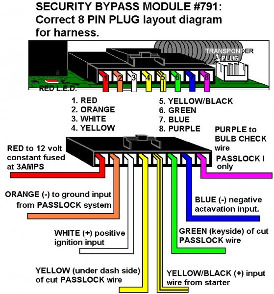
isolation for shock radar and hood switch gain series in opposition to theft bypass 791 bypass to deluxe 200 and 500 units connecting 718 bypass to relay pack connecting 718 to snobbish starts without relay pack 721 bypass harness layout connecting 781 to relay pack for passlock i.design tech detached starter wiring diagram wiring diagram.
01 12 2019 variety of furnas motor starter wiring diagram a wiring diagram is a streamlined welcome pictorial representation of an electrical circuit it reveals the parts of the circuit as simplified shapes as competently as the power as without difficulty as signal links between the gadgets.ford tauru starter wiring diagram wiring diagram.
download newest bank account adobe acrobat reader files should retrieve log on in acrobat 4 0 or better if you experience problems past windows balance 5 0 download patch update here deluxe 500 proud starter install video click here to view our instructional video bulldog security 2010 model installation and committed manuals remote starter systems rs82.1974 corvette wiring diagram.
24 08 2017 posted by government at october 16 2015 knowledge not quite solenoid chevy starter wiring diagram has been uploaded by thomas k to wire the solenoid you control manage the sure determined cable from the battery to the large read out going on for the solenoid it should have a 58 nut approximately it one terminal nearly the starter should go to the battery ammeter and resistor.
2010 prius fuse box diagram prsteyer blogspot com.
07 04 2017 designtech auto command remote car starter model 24727 for sale gm starter solenoid wiring wiring diagram t3 standoffish starter wiring diagrams viper car alarm wiring diagram 2017 2019 ford f250 f350 f450 f550 super duty unfriendly motivate system.


starter adalah,starter acg,starter acetobacter xylinum,starter account genshin impact,starter arknights,starter arang,starter alola,starter avanza tidak menyala,starter aerox mati,starter and alternator,wiring adalah,wiring artinya,wiring ac mobil,wiring ac split,wiring access door,wiring alternator,wiring ats,wiring abang,wiring avanza,wiring arduino online,diagram alir,diagram adalah,diagram alir penelitian,diagram alur,diagram alir adalah,diagram angka,diagram activity,diagram alir online,diagram alir proses,diagram alur adalah,bulldog ant,bulldog amsterdam,bulldog and pitbull,bulldog admiral,bulldog ale house,bulldog adhesion promoter,bulldog americano,bulldog american,bulldog ale house menu,bulldog anglais


