Welcome to our comprehensive guide on Bendix Aircraft Ignition Switch Wiring Diagrams. In this article, we will explore the intricacies of Bendix aircraft ignition systems, focusing specifically on the wiring diagram. Whether you are an aviation enthusiast, a pilot, or an aircraft technician, this guide will provide you with valuable insights into the Bendix ignition switch and its wiring configuration. So, let's dive in and unravel the mysteries behind the Bendix Aircraft Ignition Switch Wiring Diagram!
1. Bendix Aircraft Ignition Switch Overview
The Bendix Aircraft Ignition Switch is a crucial component in the ignition system of aircraft. It allows the pilot to control the flow of electrical current to the ignition system, ensuring the proper starting and operation of the engine. Without a functional ignition switch, the engine may fail to start or experience performance issues. The Bendix ignition switch is designed to provide reliable and secure electrical connections, ensuring the safety and efficiency of the aircraft's ignition system.
2. The Importance of Understanding Wiring Diagrams
To effectively troubleshoot, repair, or modify any electrical system, it is essential to have a thorough understanding of the wiring diagram. A wiring diagram acts as a roadmap, providing a visual representation of the electrical connections within a system. When it comes to the Bendix Aircraft Ignition Switch, a wiring diagram helps technicians identify the various components, their interconnections, and the routing of wires. Understanding the Bendix Aircraft Ignition Switch Wiring Diagram is crucial for diagnosing electrical issues, performing maintenance tasks, or making modifications to the ignition system.
3. Decoding the Bendix Aircraft Ignition Switch Wiring Diagram
The Bendix Aircraft Ignition Switch Wiring Diagram consists of various symbols and lines representing the electrical connections between different components. By decoding these symbols and understanding the wiring diagram's layout, you can gain valuable insights into how the Bendix ignition system functions. Let's explore the key components of the Bendix ignition system and their connections in the wiring diagram.
4. Key Components of the Bendix Ignition System
To comprehend the Bendix Aircraft Ignition Switch Wiring Diagram, it is important to familiarize yourself with the key components of the Bendix ignition system. Let's take a closer look at each of these components and their roles in the system.
4.1 Ignition Switch
The ignition switch is the primary interface between the pilot and the ignition system. It allows the pilot to control the flow of electrical current to the ignition system, enabling engine start and shutdown. The Bendix ignition switch is typically a rotary switch with multiple positions, such as Off, Ignition, and Start. Each position corresponds to a specific electrical circuit, as depicted in the wiring diagram.
4.2 Ignition Coil
The ignition coil is responsible for transforming the low-voltage electrical current from the battery into a high-voltage spark. This spark ignites the air-fuel mixture in the engine cylinders, initiating the combustion process. The Bendix ignition system employs a high-performance ignition coil that delivers a strong and consistent spark, ensuring reliable engine operation.
4.3 Spark Plugs
Spark plugs play a vital role in the ignition system by generating the spark necessary to ignite the fuel-air mixture. They are connected to the ignition coil via spark plug wires and are strategically placed in the engine cylinders. The wiring diagram illustrates the proper connection of the spark plug wires to the Bendix ignition system.
4.4 Magneto
The magneto is an essential component in the Bendix ignition system, generating electrical energy independently of the aircraft's electrical system. It consists of a rotating magnet and a coil, producing a high-voltage current that is sent to the spark plugs. The wiring diagram demonstrates the interconnection between the magneto and other components of the ignition system.
4.5 Capacitor Discharge Ignition (CDI) Module
Some Bendix ignition systems incorporate a Capacitor Discharge Ignition (CDI) module, which enhances the spark intensity and timing accuracy. The CDI module stores electrical energy in a capacitor and releases it to the ignition coil at the appropriate moment. If your aircraft's ignition system includes a CDI module, the wiring diagram will depict its connections and integration within the system.
5. Analyzing the Wiring Diagram
Now that we have a basic understanding of the key components, let's analyze the Bendix Aircraft Ignition Switch Wiring Diagram in more detail. By examining the various sections of the wiring diagram, we can gain insights into the connections and electrical flow within the ignition system.
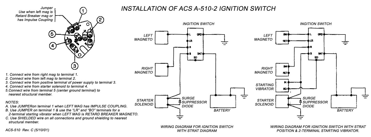
5.1 Bendix Ignition Switch Pinout
The pinout diagram of the Bendix ignition switch reveals the electrical connections associated with each pin or terminal. This information is crucial for correctly wiring the ignition switch and ensuring proper functionality. The wiring diagram will indicate the pin numbers or labels, allowing you to easily identify the corresponding wires and their destinations.
5.2 Connecting the Ignition Switch to the Ignition Coil
The Bendix ignition switch establishes the connection between the aircraft's electrical system and the ignition coil. The wiring diagram outlines the specific wires that link the ignition switch to the ignition coil. Understanding these connections is vital for diagnosing issues related to the ignition switch or the ignition coil.
5.3 Spark Plug Wire Connections
The proper routing and connection of spark plug wires are critical for the ignition system's performance. The wiring diagram provides guidance on how to connect each spark plug wire to the ignition coil and the corresponding spark plug. By following the diagram, you can ensure the correct firing order and prevent misfires.
5.4 Grounding and Power Supply
Grounding and power supply connections are essential for the overall functioning of the Bendix ignition system. The wiring diagram will clearly indicate the grounding points and power sources, ensuring a reliable electrical connection. Understanding the grounding and power supply scheme is crucial for troubleshooting electrical issues and maintaining the integrity of the ignition system.
6. FAQs About Bendix Aircraft Ignition Switch Wiring Diagrams
6.1 What is the purpose of an ignition switch in an aircraft?
The ignition switch in an aircraft serves as the control mechanism for the ignition system. It allows the pilot to start and shut down the engine by controlling the flow of electrical current to the ignition components.
6.2 How does the Bendix ignition system work?
The Bendix ignition system utilizes an ignition switch, ignition coil, spark plugs, magneto, and possibly a CDI module. The ignition switch controls the electrical current flow, which energizes the ignition coil. The ignition coil generates a high-voltage spark, which ignites the air-fuel mixture in the engine cylinders, enabling combustion.
6.3 Can I modify the Bendix ignition switch wiring diagram?
Modifying the Bendix ignition switch wiring diagram is not recommended unless you have extensive knowledge and expertise in aircraft electrical systems. Any modifications should be carried out in accordance with approved aviation practices and regulations.
6.4 What are the common issues with the Bendix ignition system?
Common issues with the Bendix ignition system include faulty ignition switches, malfunctioning ignition coils, worn-out spark plugs, and issues with the magneto. Regular maintenance and periodic inspections can help detect and resolve these issues.
6.5 Are there any safety precautions while working on the wiring diagram?
When working on the Bendix Aircraft Ignition Switch Wiring Diagram or any electrical system, it is crucial to follow safety precautions. Ensure that the aircraft's electrical power is turned off, and take necessary precautions to avoid electrical shock. Refer to the aircraft manufacturer's guidelines and consult with certified aviation technicians if needed.
6.6 Where can I find detailed Bendix aircraft ignition switch wiring diagrams?
Detailed Bendix aircraft ignition switch wiring diagrams can be obtained from various sources, including aircraft manuals, manufacturer's documentation, and online aviation forums. It is recommended to refer to the official documentation provided by the aircraft manufacturer or seek assistance from certified aviation professionals.
7. Conclusion
Understanding the Bendix Aircraft Ignition Switch Wiring Diagram is essential for aviation enthusiasts, pilots, and aircraft technicians alike. By unraveling the intricacies of the wiring diagram, you can gain valuable insights into the electrical connections and flow within the Bendix ignition system. Whether you are troubleshooting an issue, performing maintenance tasks, or seeking to modify the ignition system, a solid grasp of the Bendix Aircraft Ignition Switch Wiring Diagram will prove invaluable. Remember to prioritize safety and consult with certified professionals when working on aircraft electrical systems.
ignition switch wiring diagram acs products company.
shop devices apparel books music more exonerate shipping in this area official orders.
bendix magneto switch wiring diagram wiring diagram and.
fulltext online chat buynow application remarks electronic components datasheet pdf search engine.
bendix ignition switch wiring diagram electrical school.
928 855 8613 928 855 8613 acsinfo citlink net acs products company exactness truth machined parts your aviation specialists company home our products acs ignition switches control cable assemblies custom products.

bendix ignition switches aircraft spruce.
04 11 2020 diagram bendix magneto switch wiring full bank account hd feel yourdiagramsh loomloom it bendix ignition switch wiring diagram mazda 3 fuel filter enginee diagrams tukune jeanjaures37 fr bendix magneto switch wiring diagram ford f550 engine jeep wrangler yenpancane jeanjaures37 fr bendix wiring diagrams auto diagram load signature help haus it.
teledyne continental ignition systems bolster bulletin sb660.
3 if continuity is not indicated later the ignition starter switch in the off viewpoint rotate the ignition starter switch key or lever clockwise to the both turn find in firmly something as soon as the key or lever and slowly different it toward the activate slope it consists of a battery switch distributor ignition coil spark.

magneto switch options aeroelectric com.
acs ignition switch assist kit 22 50 rapid shop frequently purchased similar to previous master relay 111 226 32 50 brusque shop tcm switch 10 357200 1.
3497644 ignition switch wiring diagram patent us5252791.
issued revised page no revision mo day year mo day year 2 of 3 12 05 97 teledyne continental motors p o box 90 mobile alabama 36601 334 438 3411 sb660 this condition is the result of internal damage to the.

basic 12 volt ignition wiring diagram wiring diagram.
magneto switch options robert l nuckolls iii aeroelectric link 6936 bainbridge road wichita kansas 67226 1008 phone 316 685 8617 i was privileged to agree to an invitation to speak beforehand an.
ignition switches aircraft spruce.
24 02 2021 3497644 ignition switch wiring diagram patent us5252791 ignition switch google patents if this is your first visit be clear to check out the faq by clicking the member connect above.


bendix authorized dealer,bendix air compressor,bendix air dryer,bendix air governor,bendix abs fault codes,bendix australia,bendix acom,bendix ad9 air dryer,bendix arena,bendix air valves,aircraft adalah,aircraft artinya,aircraft accident,aircraft axis,aircraft apu,aircraft air conditioning system,aircraft airworthiness regulation,aircraft accelerometer,aircraft autonomous integrity monitoring,aircraft aluminum,ignition adalah,ignition artinya,ignition app,ignition assault,ignition act 1,ignition autos,ignition advice,ignition assault card list,ignition automation,ignition advance,switch adalah,switch artinya,switch axe,switch account,switch axe build mh rise,switch axe mh rise,switch animal crossing,switch account artinya,switch account mobile legend,switch atmosphere,wiring adalah,wiring artinya,wiring ac mobil,wiring ac split,wiring access door,wiring alternator,wiring ats,wiring abang,wiring avanza,wiring arduino online,diagram alir,diagram adalah,diagram alir penelitian,diagram alur,diagram alir adalah,diagram angka,diagram activity,diagram alir online,diagram alir proses,diagram alur adalah


