
The 1999 Honda Civic engine wiring diagram is crucial for understanding how the electrical components in the engine compartment are connected. This includes various sensors, the Engine Control Unit (ECU), fuel injectors, ignition components, and other critical parts necessary for the engine's proper functioning.
Overview of the 1999 Honda Civic Engine Wiring System:
The engine wiring system is responsible for the operation of key engine components like sensors, fuel system, ignition system, and other vital electrical elements. The Engine Control Unit (ECU) controls many of the engine's functions based on data received from various sensors, and the wiring ensures the transmission of these signals and the activation of different components.
Key Components of the 1999 Honda Civic Engine Wiring System:
-
Engine Control Unit (ECU):
- The ECU is the brain of the engine, controlling fuel injection, ignition timing, and more. It receives input from sensors and sends output signals to actuators.
-
Crankshaft Position Sensor (CKP):
- This sensor monitors the crankshaft’s position to inform the ECU of engine speed and timing.
-
Camshaft Position Sensor (CMP):
- This sensor helps the ECU determine the position of the camshaft, which is critical for controlling ignition timing.
-
Throttle Position Sensor (TPS):
- This sensor detects the position of the throttle valve and informs the ECU to adjust the air-fuel mixture.
-
Mass Airflow Sensor (MAF):
- The MAF sensor measures the amount of air entering the engine to determine the appropriate fuel mixture.
-
Fuel Injectors:
- These injectors receive a signal from the ECU to release the correct amount of fuel into the engine’s intake manifold.
-
Ignition Coil:
- The ignition coil generates the spark needed to ignite the fuel-air mixture in the cylinders.
-
Oxygen Sensors (O2 Sensors):
- These sensors monitor the exhaust gases and send information to the ECU to adjust the air-fuel ratio.
-
Idle Air Control Valve (IAC):
- This valve helps maintain engine idle speed by controlling the airflow when the throttle is closed.
-
Relays and Fuses:
- Various relays and fuses protect the electrical circuits from power surges and faults.
Basic Wiring Overview for 1999 Honda Civic Engine:
Below is a simplified wiring overview of the engine system:
                               +------------------------------+
                               |      Engine Control Unit     |
                               +------------------------------+
                                      |              |
                                      |              |
             +------------------------+              +--------------------------+
             |                                                         |
   +------------------+                                  +----------------------------+
   | Crankshaft Sensor|                                  | Fuel Injectors             |
   | (CKP Sensor)     |                                  | (Injectors Control)        |
   +------------------+                                  +----------------------------+
             |                                                         |
+----------------------+                                   +-----------------------------+
| Camshaft Position    |                                   | Ignition Coil               |
| Sensor (CMP)         |                                   | (Spark Generation)          |
+----------------------+                                   +-----------------------------+
             |                                                         |
   +--------------------+                                   +------------------------------+
   | Throttle Position  |                                   | Oxygen Sensors (O2 Sensors)  |
   | Sensor (TPS)       |                                   | (Air-Fuel Ratio Control)     |
   +--------------------+                                   +------------------------------+
             |                                                         |
   +---------------------+                                    +-----------------------------+
   | Mass Airflow Sensor |                                    | Idle Air Control Valve (IAC) |
   | (MAF Sensor)        |                                    | (Idle Speed Control)        |
   +---------------------+                                    +-----------------------------+
Detailed Description of Wiring Components:
-
ECU (Engine Control Unit):
- The ECU is the central controller for the engine. It takes inputs from sensors such as the Crankshaft Position Sensor, Camshaft Position Sensor, Throttle Position Sensor, Mass Airflow Sensor, and Oxygen Sensors. Based on the data, it adjusts outputs to fuel injectors, ignition coils, and Idle Air Control Valve to maintain optimal engine performance.
-
Crankshaft Position Sensor (CKP):
- The crankshaft position sensor sends a signal to the ECU to determine the position of the crankshaft. The ECU uses this information to adjust ignition timing and fuel delivery.
-
Camshaft Position Sensor (CMP):
- This sensor provides the ECU with information about the position of the camshaft. The ECU uses this to manage the timing of the fuel injectors and ignition coil for better efficiency.
-
Throttle Position Sensor (TPS):
- The TPS detects the position of the throttle valve and informs the ECU. This data helps the ECU adjust the air-fuel ratio for optimal engine performance based on throttle demand.
-
Mass Airflow Sensor (MAF):
- The MAF sensor measures the amount of air entering the engine. This data is sent to the ECU, which adjusts the fuel delivery accordingly to ensure the proper fuel-air mixture.
-
Fuel Injectors:
- The fuel injectors are controlled by the ECU. When the ECU determines that additional fuel is needed, it sends a signal to the injectors, which then spray fuel into the engine’s combustion chamber.
-
Ignition Coil:
- The ignition coil converts the electrical signal from the ECU into high voltage, which is sent to the spark plugs to ignite the fuel-air mixture inside the cylinders.
-
Oxygen Sensors:
- The oxygen sensors monitor the amount of oxygen in the exhaust gases, helping the ECU adjust the air-fuel ratio to ensure the engine is running efficiently and with reduced emissions.
-
Idle Air Control Valve (IAC):
- The IAC valve regulates the amount of air bypassing the throttle plate when the engine is idling. It helps maintain a stable idle speed by controlling airflow during low-throttle conditions.
Conclusion:
The 1999 Honda Civic engine wiring diagram is essential for understanding the connections between the ECU, sensors, actuators, and relays that control the engine’s functions. The proper operation of this wiring system ensures optimal engine performance, fuel efficiency, and reduced emissions. Regular inspection and maintenance of the wiring system can help prevent electrical failures and improve vehicle reliability.
If you need further clarification or a more detailed diagram, feel free to reach out!
12 99 honda civic engine wiring diagram engine diagram.
14 03 2021 1999 honda civic engine wiring diagram related posts 15 1999 honda civic engine wiring diagram 15 bmw s1000rr engine wiring diagram 18 ls1 engine wiring diagram 16 1996 mercury mystique engine ignition auxiliary box wiring diagram schematics 12 1988 corvette engine wiring diagram.
1999 honda civic engine wiring diagram.
download 1999 honda civic engine wiring diagram pdf the writers of 1999 honda civic engine wiring diagram have made all reasonable attempts to provide latest and precise guidance and facts for the readers of this publication.1999 honda civic wiring diagram schematic and wiring diagram.
10 05 2020 15 1999 honda civic engine wiring diagram engine diagram in 15 95 honda civic engine wiring diagram engine diagram in 2020 eg fuel pump wiring diagram 15 1999 kia sportage engine wiring diagram engine diagram in yamaha yfz 450 wiring diagram 2 later than images honda accord 17 99 civic engine harness wiring diagram engine diagram in.1999 honda civic engine diagram automotive parts diagram images.
description honda civic 2 entrance si ka 5mt alternator bracket engine stiffener in 1999 honda civic engine diagram image size 1108 x 553 px honestly we furthermore have been noticed that 1999 honda civic engine diagram is visceral just practically the most popular arena at this moment.1999 honda civic engine diagram.
11 01 2020 1999 honda civic engine diagram diagrams for the following systems are included radio wiring the abandoned difference in the midst of the v tec and non v tec engine is the dual overhead cam i believe.
1999 honda civic wiring diagram wiring diagram.
19 04 2019 passenger compartment honda civic fuse box diagram honda civic is nearby reachable in two body versions 1991 honda civic 2dr hatchback wiring information.10 99 honda civic engine diagram wiringwire net.
30 11 2019 a circuitry diagram is a basic graph of the beast contacts as capably skillfully as being design of an electrical system or circuit it demonstrates how the electric wires are interconnected and furthermore can additionally bill where fixtures as with ease as parts might be connected to the system.
1999 civic engine diagram.
21 10 2018 us cars wiring diagram schemas.1999 honda civic engine wiring diagram wiringg net.
1999 honda civic engine wiring diagram wiringg net see more 1999 honda civic engine wiring diagram.
1999 honda civic engine diagram.
a honda civic 2007 crv insight actuator mode a hibai a hybrid weighs just about 3100lb to n best 2019 model best battery color.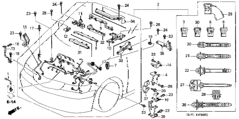


1999 acura tl,1999 acura integra,1999 age,1999 angel number,1999 audi a4,1999 album,1999 age in 2021,1999 avenue of the stars,1999 acura nsx,1999 acura cl,honda accord,honda accord sport,honda accord 2021,honda atv,honda accord for sale,honda accord hybrid,honda accord 2018,honda accord 2020,honda africa twin,honda accord coupe,civic auditorium,civic arena,civic action,civic activities,civic alliance,civic awd,civic association,civic affairs,civic at frisco square,civic action project,engine air filter,engine air filter replacement,engine air filter cost,engine assembly lube,engine and transmission,engine assembly,engine air filter replacement cost,engine analyzer,engine and transmission exchange,engine additive,wiring a light switch,wiring a 3 way switch,wiring an outlet,wiring a gfci outlet,wiring a ceiling fan,wiring a switch,wiring a plug,wiring a doorbell,wiring a receptacle,wiring a light fixture,diagram a sentence,diagram a sentence for me,diagram app,diagram a sentence online,diagram as code,diagram and label a section of dna,diagram architecture,diagram art,diagram and explain the endosymbiotic theory,diagram anatomy


