2003 Honda Civic Cluster Wiring Diagram: A Comprehensive Guide
The 2003 Honda Civic is one of the most popular and reliable vehicles on the road, known for its fuel efficiency, sleek design, and durable performance. Like any modern vehicle, the Civic relies on a vast network of electrical systems that control various aspects of the vehicle’s operation, including its instrument cluster. The instrument cluster is an essential component of the car's dashboard, displaying critical information such as speed, engine temperature, fuel level, and warning indicators. If you ever encounter electrical issues with the cluster, understanding the wiring diagram can help you troubleshoot and repair the system efficiently.
In this article, we will break down the 2003 Honda Civic cluster wiring diagram, exploring how the instrument cluster functions, how the wiring is structured, and how to read the diagram for effective diagnostics and repairs.
Understanding the Instrument Cluster
Before delving into the wiring diagram, it’s important to understand what an instrument cluster is and how it works. The instrument cluster, often referred to as the dashboard cluster or the gauge cluster, is a set of gauges and lights that display important information to the driver.
The 2003 Honda Civic’s instrument cluster includes:
- Speedometer: Displays the vehicle’s speed.
- Tachometer: Displays the engine’s RPM (Revolutions Per Minute).
- Fuel Gauge: Shows the level of fuel in the tank.
- Engine Temperature Gauge: Indicates the temperature of the engine coolant.
- Warning Lights: These include the check engine light, oil pressure light, battery light, and other indicators that alert the driver to potential issues.
The instrument cluster works by receiving data from various sensors and electrical components throughout the vehicle, then displaying that information to the driver. If one of these components malfunctions or if there is an issue with the wiring, the cluster may not function correctly.
Key Components in the Instrument Cluster Wiring System
To understand the wiring diagram, let’s first break down the key components involved in the instrument cluster’s electrical system:
-
Power Supply: The instrument cluster is powered by the vehicle’s electrical system. This power is typically supplied from the car’s battery or alternator.
-
Grounding: Grounding is crucial for completing the electrical circuit. The instrument cluster needs to be properly grounded to function correctly.
-
Sensors: Various sensors throughout the vehicle send signals to the instrument cluster. These include the speed sensor (for the speedometer), the engine coolant temperature sensor (for the engine temperature gauge), and the fuel level sensor (for the fuel gauge).
-
Control Module: The 2003 Honda Civic features an onboard diagnostic system (OBD-II) that communicates with the instrument cluster. This system sends signals to the cluster regarding warning lights and engine performance.
-
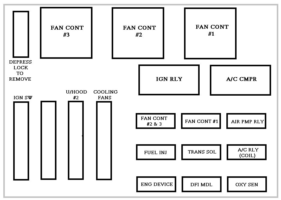
Wiring Harness: The wiring harness connects all of the components, carrying signals to and from the instrument cluster. A damaged or faulty wiring harness can cause erratic or non-functional display readings.
The Wiring Diagram
The wiring diagram for the 2003 Honda Civic’s instrument cluster is a complex schematic that shows the connections between the instrument cluster and other components. The diagram is typically divided into several sections, with each section representing a different aspect of the electrical system.
While it’s difficult to provide the complete wiring diagram here, we can go over the general layout and the connections that are most critical to the functioning of the instrument cluster.
1. Power and Ground Circuits
The instrument cluster is powered by the vehicle’s electrical system. In the 2003 Honda Civic, power typically comes from the ignition switch, which sends power to the cluster when the key is turned to the “on” position. A dedicated ground circuit completes the circuit, ensuring proper function.
The power and ground circuits are critical to the proper functioning of the cluster. Without power, the gauges will not function, and without a proper ground, electrical signals could be interrupted or cause erratic behavior.
2. Speedometer Circuit
The speedometer receives its signal from a Vehicle Speed Sensor (VSS) located on the vehicle’s transmission. The VSS sends a signal to the Engine Control Unit (ECU), which processes the data and sends it to the instrument cluster. The wiring between the ECU and the instrument cluster is usually routed through the car’s main wiring harness.
In the wiring diagram, you will find that the speedometer is connected to a specific wire for the VSS signal. If the speedometer is malfunctioning, it may be due to a broken wire, faulty sensor, or a problem with the ECU.
3. Tachometer Circuit
The tachometer, which measures the engine's RPM, relies on the signals from the Engine Control Module (ECM). The ECM processes the crankshaft position sensor’s data and sends it to the instrument cluster via a designated circuit. This allows the tachometer needle to indicate engine RPM.
The tachometer’s wiring is closely tied to the engine’s electrical system. A malfunctioning tachometer is often caused by a poor connection between the ECM and the instrument cluster or a fault in the engine’s sensor wiring.
4. Fuel Gauge Circuit
The fuel gauge is connected to the fuel level sensor in the fuel tank. The sensor sends a signal to the instrument cluster, indicating how much fuel is in the tank. The wiring between the fuel sensor and the instrument cluster runs through the car’s wiring harness.
The fuel gauge wiring is typically routed along with other sensor circuits, but it’s essential to ensure that there are no broken or damaged wires that could result in incorrect fuel readings.
5. Temperature Gauge Circuit
The temperature gauge uses a signal from the engine coolant temperature (ECT) sensor. This sensor measures the temperature of the coolant as it circulates through the engine. The ECT sensor sends a voltage signal to the ECU, which then relays this information to the instrument cluster.
A faulty temperature gauge may indicate a problem with the wiring between the ECT sensor and the instrument cluster or an issue with the ECU’s processing of the data.
6. Warning Lights and Indicators
The instrument cluster also includes various warning lights, such as the check engine light, oil pressure light, and battery light. These lights are typically controlled by the ECU and activated when the car’s diagnostic system detects an issue. The wiring for these lights connects the instrument cluster to the car’s sensors and control modules.
The warning light circuit is often routed through the ECU, which triggers the appropriate light when a problem is detected.
Diagnosing Issues with the Instrument Cluster
If you're having trouble with your instrument cluster, there are a few common issues to check for based on the wiring diagram:
-
No Power: If none of the gauges or lights are working, check the power and ground circuits. A blown fuse or a disconnected wire can interrupt the power supply to the cluster.
-
Erratic or Incorrect Readings: If the gauges are reading incorrectly or fluctuating erratically, there may be an issue with the sensor wires or the control module. Inspect the wiring connections for loose or corroded connections.
-
Warning Lights Not Illuminating: If the warning lights aren’t illuminating when they should, the problem could be with the ECU or the wiring connecting the warning light circuit.
-
No Backlighting: If the instrument cluster is not lighting up properly at night, it could be a problem with the backlighting or the circuit that controls the lights.
Conclusion
The 2003 Honda Civic instrument cluster wiring diagram is an essential tool for diagnosing and repairing electrical issues related to the dashboard gauges and warning lights. Understanding the wiring and how each component communicates with the cluster will help you troubleshoot problems more effectively. Always refer to the diagram for the correct wiring connections and ensure that all electrical components are functioning properly.
If you're not comfortable performing electrical work on your vehicle, it's always a good idea to consult a professional mechanic or technician who can help resolve any issues with your instrument cluster. Proper maintenance and prompt repairs will ensure that your Civic continues to run smoothly for years to come.
I hope this helps! Let me know if you need more information or further clarification on any part.
car electrical wiring diagrams automotive diagram guide 2020.
find used civic honda search faster better smarter at zapmeta now.2003 toyota tundra stereo wiring diagram mizzxerraa.
get hoonda civic pull off instant mood info.1955 chevy bel air ignition switch wiring diagram mizzxerraa.
search for used honda civic at mysearchexperts check out results for used honda civic.


2003 acura tl,2003 acura mdx,2003 audi tt,2003 audi a4,2003 acura tl type s,2003 acura rsx,2003 avalanche,2003 age,2003 acura,2003 accord,honda accord,honda accord sport,honda atv,honda accord for sale,honda accord 2018,honda accord 2020,honda africa twin,honda accord coupe,honda accord 2022,honda accessories,civic auditorium,civic arena,civic action,civic activities,civic alliance,civic awd,civic association,civic affairs,civic at frisco square,civic action project,cluster a personality disorders,cluster analysis,cluster a,cluster autoscaler,cluster app,cluster analysis in r,cluster api,cluster analysis example,cluster a b c,cluster a personality,wiring a light switch,wiring a 3 way switch,wiring an outlet,wiring a gfci outlet,wiring a ceiling fan,wiring a switch,wiring a plug,wiring a doorbell,wiring a receptacle,wiring a light fixture,diagram a sentence,diagram a sentence for me,diagram app,diagram a sentence online,diagram as code,diagram and label a section of dna,diagram architecture,diagram art,diagram and explain the endosymbiotic theory,diagram anatomy


