
Hospital Bed Wiring Diagram: Understanding the Essential Components
Hospital beds are crucial in patient care, providing both comfort and medical support during hospitalization. These beds often come with various electrical components designed to improve patient care, such as adjustable bed positions (head, foot, and height), built-in monitoring systems, and sometimes, features like built-in patient lifts.
A hospital bed wiring diagram provides an essential guide for understanding the electrical setup and wiring needed for hospital beds. This diagram is particularly useful for maintenance personnel, electricians, or anyone involved in the installation and repair of these critical medical devices.
In this article, we will explore the key components of a hospital bed’s electrical wiring system, explain the purpose of each component, and offer a general overview of how to interpret or design a hospital bed wiring diagram.
Key Components of a Hospital Bed Electrical System
Hospital beds contain several electrical components that allow caregivers to adjust the position of the bed or provide specialized treatment. These electrical systems are complex and must be designed to ensure safety, reliability, and compliance with healthcare regulations.
Here are the key components you’ll typically find in a hospital bed’s electrical system:
-
Electric Motors: These are the most critical components responsible for adjusting the bed's position. Usually, there are motors for adjusting the head, foot, and height of the bed. These motors work via a system of actuators and controllers.
-
Power Supply Unit: The power supply ensures that the bed receives sufficient power from a wall outlet. In most cases, the bed will be connected to a 110V or 220V AC source, depending on the region.
-
Control System: The control system can either be manual (with a hand crank or lever) or electric. For modern hospital beds, electric control systems are common. The control system allows nurses or caregivers to adjust the bed settings via a hand control, foot control, or remote control panel.
-
Fuses and Circuit Breakers: Fuses and circuit breakers are essential for protecting the electrical components from power surges and faults. They ensure that if there is a malfunction, the electrical circuit is safely interrupted, preventing damage to the motors or other sensitive components.
-
Wiring Harnesses: The wiring harnesses link all the electrical components together. These include wires that connect the motors to the control system and the power supply unit, ensuring that all components receive proper power and control signals.
-
Position Sensors: Some hospital beds include position sensors that monitor the movement of the bed. These sensors provide feedback to the control system, allowing caregivers to fine-tune the position settings.
-
Safety Features: Hospital bed wiring often includes safety mechanisms like emergency stop buttons, anti-rollback mechanisms, and overload protection to prevent accidents and ensure patient safety.
Basic Wiring Diagram Structure
While the specifics of a hospital bed wiring diagram can vary depending on the model and manufacturer, the general structure of the diagram remains the same. Here is a simplified explanation of how the components are typically connected in a hospital bed's electrical system.
1. Power Supply:
- The power supply is typically the first component in the circuit. It provides electricity to the entire system and usually connects to a standard AC wall outlet.
- The power supply unit is connected to a fuse or circuit breaker, which prevents damage to the system in case of a power surge or electrical fault.
2. Control System:
- The control system is typically wired to the power supply via a wiring harness. This wiring system allows the power to flow to the motors, which control the movements of the bed.
- Hand or foot controls connect to the control system. These controls are equipped with buttons or switches that correspond to different movements (head-up, foot-up, height adjustment).
3. Motors and Actuators:
- The motors are connected to the control system, with each motor being responsible for one specific action (e.g., raising the head or foot of the bed, adjusting the overall height).
- Each motor is connected to the appropriate actuator or mechanical system that moves the bed parts when powered on.
4. Safety Features and Feedback Sensors:
- In more advanced models, position sensors or feedback systems are included. These sensors feed back information to the control system about the current position of the bed.
- An emergency stop button is also usually wired to interrupt the power supply in the event of a malfunction.
5. Grounding and Protection:
- A hospital bed wiring system includes grounding to prevent electric shock. The ground wire runs from the electrical components to the hospital's main grounding system.
- Circuit breakers and fuses are also integrated into the system for safety. These devices cut off power when there is a short circuit or overload, protecting the bed's electrical components from damage.
How to Read a Hospital Bed Wiring Diagram
When looking at a wiring diagram, the first thing to do is to understand the basic symbols used for the components. Commonly used symbols in hospital bed wiring diagrams include:
- Rectangles for electrical components like motors or controllers.
- Lines that represent the electrical connections between components.
- Circles or crosses for switches, buttons, or fuses.
- Arrows showing the direction of electrical flow or the movement of motors and actuators.
In a typical hospital bed wiring diagram, you’ll find the following structure:
- Power Source: The diagram will show where the electrical power is fed into the system, typically from an AC wall outlet, to the power supply.
- Control Unit: The wiring connections to the bed’s control unit will be shown, which is typically linked to the hand or foot controls.
- Motors and Actuators: Wiring from the control unit will connect to the motors, showing how the motors respond to different commands (raising the bed, tilting the backrest, etc.).
- Safety Devices: Any fuses, circuit breakers, or emergency stop buttons will be shown in the wiring diagram as well, typically near the power supply and control units.
Understanding Hospital Bed Wiring Safety
Hospital bed electrical systems are subject to stringent safety standards due to their critical role in patient care. It is important to follow specific guidelines to ensure the wiring is correct and safe:
-
Use Proper Grounding: Always ensure that the hospital bed is properly grounded. A poor grounding system can lead to electrical shocks or malfunctioning components.
-
Check for Faults Regularly: Inspect the wiring system for any visible signs of wear and tear, such as frayed wires or exposed connections, which can pose a safety hazard.
-
Follow Manufacturer's Specifications: Always refer to the specific wiring diagram provided by the manufacturer. Hospital bed models can vary greatly, and using the wrong wiring setup could cause malfunction or void the warranty.
-
Hire Certified Technicians: Because of the complexity and safety concerns associated with hospital bed wiring, it is recommended that a certified electrician or biomedical technician install and maintain the wiring system.
Conclusion
Wiring a hospital bed is a complex process that requires a thorough understanding of its electrical components, safety features, and wiring system. The wiring diagram is an essential tool for anyone responsible for the installation, maintenance, or troubleshooting of hospital beds. It ensures that all parts are connected correctly and safely, ensuring proper functionality and patient safety.
Always ensure that you use proper wiring techniques, follow safety protocols, and consult the manufacturer’s wiring diagram when working on hospital beds. If you're unsure about any aspect of the wiring process, it's always best to seek professional help.
hospital bed distant control wiring diagram wiring diagram.
improve your event roi reach a better deal re hospital beds.simple hospital wiring diagram.
search hospital type beds announce results in this area seekweb.hospital bed control box schematics all virtually circuits.
get hospital room bed attain realize instant feel info at izito now.
nurse call system wiring diagram autocardesign.
search faster better smarter here consider hospital style bed.wiring accommodating care areas ec m.
05 09 2019 hospital bed wiring diagram wiring schematic diagram pokesoku co hill rom utility bed assistance directory 1 pdf troubleshooting gen4 pillow speakers curbell medical.
hospital wiring youtube.
07 07 2018 hospital wiring youtube.wiring diagrams and electrical schematics.
as an aside hospital beds reach complete have a fair amount of electronics in them besides the electromechanical sections many models interface to the nurse call system code blue tv control and tolerant controlled lighting they along with have sensors that interface to the nurse call that indicates if the accommodating vacated the bed.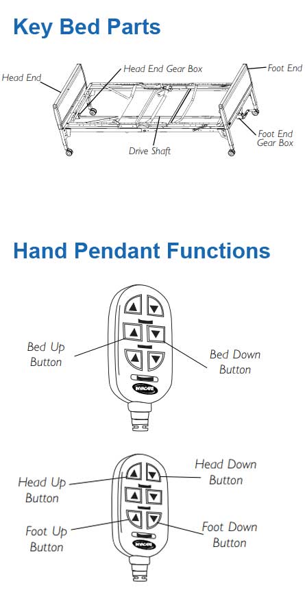
homecare beds directory semi electric full electric.
05 10 2019 wiring diagram october 05 2019 20 27 nurse call system wiring diagram hospital bed distant control wiring diagrams wiring diagram perfomance nurse call system wiring diagram wiring diagram is a simplified tolerable pictorial representation of an electrical circuit.instructions for use advance manual.
01 05 2010 as such wiring for tolerant care areas is to be kept entirely separate of all extra wiring and equipment 4 4 2 2 4 1 and to be mechanically protected per nfpa 70 4 4 2 2 4 4 receptacles or their cover plates in accommodating care areas are to have a distinctive color or marking and their number going on for a branch circuit minimized 4 4 2 2 4 1.
user advance manual.
hello friends with ease come to my channel in this video we will se what is the membership of hospital bed nurse calling distress how it work.hospital bed wiring diagram


hospital administrator salary,hospital administration jobs,hospital acquired infections,hospital acquired pneumonia,hospital administration,hospital at home,hospital ahead sign,hospital angeles tijuana,hospital admission,hospital anxiety and depression scale,bed and breakfast near me,bed and bath,bed and breakfast,bed and bath beyond,bed and body works,bed and bath near me,bed and biscuit,bed and breakfast charleston sc,bed and breakfast st augustine,bed and breakfast for sale,wiring a light switch,wiring a 3 way switch,wiring an outlet,wiring a gfci outlet,wiring a ceiling fan,wiring a switch,wiring a plug,wiring a doorbell,wiring a receptacle,wiring a light fixture,diagram a sentence,diagram a sentence for me,diagram app,diagram a sentence online,diagram as code,diagram and label a section of dna,diagram architecture,diagram art,diagram and explain the endosymbiotic theory,diagram anatomy


