“Industrial solar wiring schematics”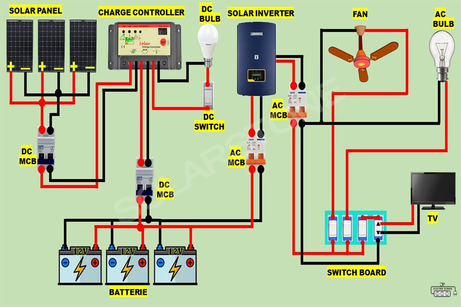
Introduction to Industrial Solar Wiring Schematics
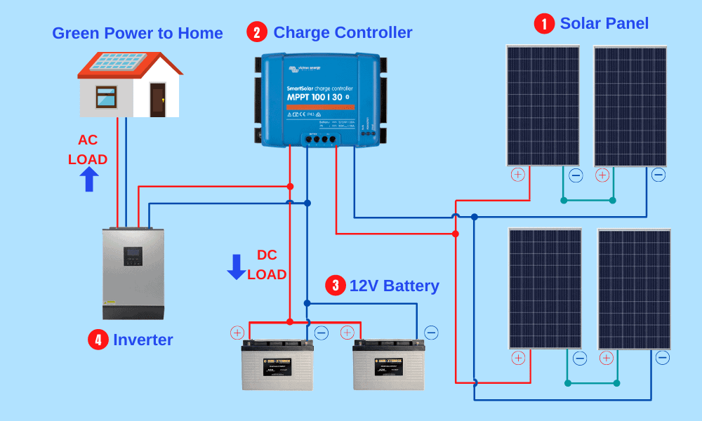
Industrial solar wiring schematics are detailed diagrams that illustrate the electrical connections and wiring of a solar power system. These schematics are essential for the design, installation, and maintenance of solar power systems, as they provide a clear visual representation of the system’s electrical architecture. Industrial solar wiring schematics typically include information on the type and rating of electrical components, such as solar panels, inverters, and batteries, as well as the wiring and connections between these components.
Importance of Industrial Solar Wiring Schematics
Industrial solar wiring schematics are critical for several reasons:
- Safety: A well-designed wiring schematic ensures that the solar power system is installed and operated safely, minimizing the risk of electrical shock, fires, and other hazards.
- Efficiency: A properly designed wiring schematic optimizes the performance of the solar power system, ensuring that energy is generated and transmitted efficiently.
- Reliability: Industrial solar wiring schematics help identify potential faults and issues, enabling maintenance personnel to troubleshoot and repair problems quickly, reducing downtime and increasing system reliability.
- Compliance: Wiring schematics are often required by regulatory bodies, such as the National Electric Code (NEC), to ensure compliance with safety standards and regulations.
Types of Industrial Solar Wiring Schematics
There are several types of industrial solar wiring schematics, including:
- String Schematics: These schematics illustrate the connection of multiple solar panels in series, forming a string.
- Array Schematics: These schematics depict the connection of multiple strings of solar panels, forming an array.
- System Schematics: These schematics provide a comprehensive overview of the entire solar power system, including the solar panels, inverters, batteries, and other components.
- Detailed Schematics: These schematics provide a detailed, component-level illustration of the solar power system, including wiring and connections.

Key Considerations for Industrial Solar Wiring Schematics
When designing and implementing industrial solar wiring schematics, several key considerations must be taken into account:

- Component Selection: The selection of electrical components, such as solar panels, inverters, and batteries, is critical to ensuring the safe and efficient operation of the solar power system.
- Wiring and Connections: The wiring and connections between components must be carefully designed and implemented to minimize losses and ensure safe operation.
- Grounding and Bonding: Proper grounding and bonding of the solar power system are essential to ensure safe operation and prevent electrical shock.
- Surge Protection: Surge protection devices (SPDs) must be installed to protect the solar power system from power surges and lightning strikes.
- Monitoring and Control: The solar power system must be monitored and controlled to optimize performance, detect faults, and prevent damage.
Designing Industrial Solar Wiring Schematics
Designing industrial solar wiring schematics requires a thorough understanding of electrical engineering principles, as well as expertise in solar power systems. The design process typically involves:
- Load Calculation: Calculating the total load of the solar power system, including the power requirements of the connected loads.
- Component Selection: Selecting the electrical components, such as solar panels, inverters, and batteries, based on the load calculation and system requirements.
- Wiring and Connection Design: Designing the wiring and connections between components, taking into account factors such as voltage drop, current carrying capacity, and safety.
- Grounding and Bonding: Designing the grounding and bonding system to ensure safe operation and prevent electrical shock.
- Surge Protection: Installing surge protection devices (SPDs) to protect the solar power system from power surges and lightning strikes.
Tools and Software for Industrial Solar Wiring Schematics
Several tools and software are available to design and create industrial solar wiring schematics, including:
- AutoCAD: A popular computer-aided design (CAD) software used to create detailed schematics and diagrams.
- SPICE: A simulation software used to model and analyze the behavior of electrical circuits.
- PVSYST: A software tool used to design and simulate solar power systems.
- Electrical CAD Software: Specialized software, such as ETAP or SKM, used to design and analyze electrical systems, including solar power systems.
Best Practices for Industrial Solar Wiring Schematics
To ensure the safe and efficient operation of solar power systems, several best practices must be followed when designing and implementing industrial solar wiring schematics:
- Follow Industry Standards: Follow industry standards, such as the NEC, to ensure compliance with safety regulations.
- Use Proper Component Ratings: Use electrical components with appropriate ratings, such as voltage and current, to ensure safe operation.
- Keep Schematics Up-to-Date: Regularly update wiring schematics to reflect changes to the solar power system.
- Use Clear and Concise Labeling: Use clear and concise labeling to ensure that the wiring schematic is easy to understand and interpret.
- Test and Validate: Test and validate the solar power system to ensure that it operates safely and efficiently.
Conclusion
Industrial solar wiring schematics play a vital role in ensuring the safe and efficient operation of solar power systems. By understanding the importance, types, and key considerations of industrial solar wiring schematics, designers and installers can create effective and reliable solar power systems. By following best practices and using specialized tools and software, the solar industry can continue to grow and evolve, providing a sustainable and renewable source of energy for generations to come.