“Solar panel to inverter wiring diagram”
Introduction to Solar Panel Systems
A solar panel system, also known as a photovoltaic (PV) system, converts sunlight into electrical energy. The system consists of multiple components, including:
- Solar Panels: These are the photovoltaic panels that convert sunlight into direct current (DC) electricity.
- Inverter: This device converts the DC electricity from the solar panels into alternating current (AC) electricity, which is usable in homes and businesses.
- Mounting System: This includes the racks, clamps, and other hardware that secures the solar panels to the roof or ground.
- Wiring and Connections: This includes the cables, connectors, and wiring diagrams that connect the solar panels to the inverter and other system components.
Understanding the Importance of Wiring Diagrams
A wiring diagram is a visual representation of the electrical connections between the solar panels, inverter, and other system components. It is essential to create a wiring diagram for several reasons:
- Safety: A wiring diagram helps ensure that the system is installed correctly, reducing the risk of electrical shock, fires, or other hazards.
- Efficiency: A well-designed wiring diagram optimizes the flow of electricity, minimizing energy losses and maximizing system performance.
- Maintenance: A wiring diagram provides a clear understanding of the system’s electrical connections, making it easier to troubleshoot and maintain the system.
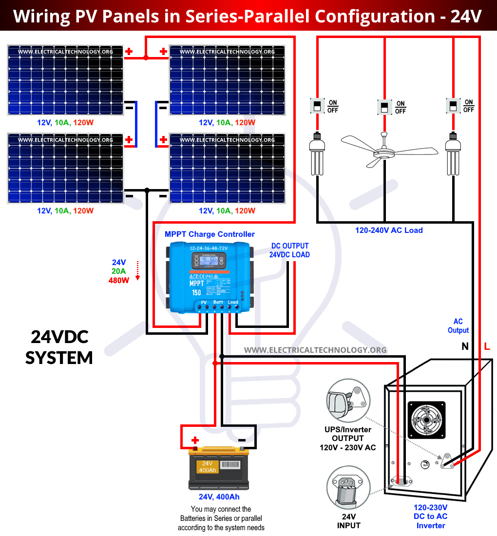
Components of a Solar Panel to Inverter Wiring Diagram
A typical solar panel to inverter wiring diagram includes the following components:
- Solar Panels: These are represented by a symbol or icon, indicating the number of panels, their orientation, and their electrical characteristics (e.g., voltage, current, and power).
- Inverter: This is represented by a symbol or icon, indicating the inverter’s model, power rating, and electrical characteristics (e.g., input voltage, output voltage, and frequency).
- DC Connectors: These connect the solar panels to the inverter, typically using MC4 connectors or similar.
- AC Connectors: These connect the inverter to the grid or load, typically using a 240V or 120V connector.
- Grounding System: This includes the grounding wires, connectors, and electrodes that connect the system to the earth, ensuring electrical safety.
- Fuses and Circuit Breakers: These protect the system from overcurrent conditions, such as short circuits or overload.

Creating a Solar Panel to Inverter Wiring Diagram
To create a wiring diagram, follow these steps:
- Determine the System Configuration: Decide on the number of solar panels, their orientation, and the inverter model.
- Choose the Components: Select the DC and AC connectors, grounding system, fuses, and circuit breakers.
- Create a Schematic Diagram: Use a software tool or drawing program to create a schematic diagram of the system, including the solar panels, inverter, and other components.
- Add Electrical Connections: Draw the electrical connections between the components, including the DC and AC connectors, grounding system, and fuses.
- Label and Annotate: Label each component and annotate the diagram with relevant electrical characteristics, such as voltage, current, and power.
Best Practices for Solar Panel to Inverter Wiring Diagrams
To ensure a safe and efficient system, follow these best practices:
- Use Standard Symbols and Notations: Use standard symbols and notations for electrical components, such as the IEEE or IEC standards.
- Label and Annotate Clearly: Label each component and annotate the diagram with clear and concise information.
- Use Color-Coding: Use color-coding to differentiate between DC and AC connections, as well as to indicate the grounding system.
- Keep it Simple and Organized: Avoid clutter and keep the diagram organized, using a clear and consistent layout.
- Verify and Validate: Verify the diagram against the system configuration and validate it against the manufacturer’s instructions and local electrical codes.
Common Mistakes to Avoid
When creating a solar panel to inverter wiring diagram, avoid these common mistakes:
- Inconsistent or Missing Labels: Failing to label components or using inconsistent labels can lead to confusion and errors.
- Incorrect or Missing Grounding: Omitting or incorrectly installing the grounding system can compromise electrical safety.
- Insufficient or Incorrect Fuses: Using insufficient or incorrect fuses can lead to overcurrent conditions and system damage.
- Poorly Designed or Executed Connections: Poorly designed or executed connections can lead to energy losses, overheating, or electrical shock.
Conclusion
A solar panel to inverter wiring diagram is a critical component of a solar power system, ensuring safe and efficient electrical connections between the solar panels, inverter, and other system components. By understanding the basics, components, and best practices for creating a wiring diagram, you can ensure a well-designed and functional system. Remember to follow standard symbols and notations, label and annotate clearly, and verify and validate the diagram against the system configuration and manufacturer’s instructions. With a well-designed wiring diagram, you can enjoy the benefits of solar power while minimizing the risks of electrical shock, fires, or system damage.


