The K24 engine is a popular choice among automotive enthusiasts for its power and reliability. Whether you're a mechanic or a car enthusiast, understanding the wiring diagram of the K24 engine can be immensely helpful in troubleshooting electrical issues, performing modifications, or simply gaining a deeper understanding of the engine's intricate electrical system. In this article, we'll explore the K24 engine wiring diagram in detail, covering its components, how to read it, and its significance in maintaining and diagnosing the engine's electrical functionality.
When it comes to working on any engine, having a comprehensive understanding of its wiring diagram is crucial. A wiring diagram is a graphical representation of the electrical circuits, connectors, and components of an engine's electrical system. In the case of the K24 engine, the wiring diagram provides a roadmap that allows technicians and enthusiasts to visualize the interconnections between various electrical components, making troubleshooting and modifications much easier.
Understanding the K24 Engine
What is the K24 Engine?
The K24 engine is a four-cylinder, inline engine manufactured by Honda. It belongs to the K-series family of engines and is known for its performance and durability. The K24 engine is commonly found in various Honda and Acura models, including the Honda Accord and Acura TSX. Its popularity among car enthusiasts is due to its impressive power output, smooth operation, and potential for aftermarket modifications.
Key Features and Specifications
The K24 engine features a displacement of 2.4 liters and utilizes Honda's advanced technologies to deliver a balance of power and fuel efficiency. It incorporates features such as variable valve timing (VTEC), which optimizes engine performance at different RPM ranges, and electronic throttle control for precise throttle response. The engine is also equipped with various sensors and actuators that play a crucial role in monitoring and controlling its operation.
Importance of a Wiring Diagram
The wiring diagram of the K24 engine holds significant importance for anyone working on the engine's electrical system. It serves as a visual representation of the engine's intricate electrical connections, helping technicians and enthusiasts identify the correct routing of wires, locate connectors, and understand the functionality of various electrical components. Whether it's diagnosing an electrical issue, performing modifications, or installing aftermarket accessories, the wiring diagram acts as a valuable reference.
Components of the K24 Engine Wiring Diagram
The K24 engine wiring diagram consists of several components that work together to ensure the engine's electrical system operates smoothly and efficiently. Let's take a closer look at some of the key components you'll find in the K24 engine wiring diagram:
Engine Control Module (ECM)
The Engine Control Module, or ECM, is the brain of the engine's electrical system. It receives inputs from various sensors and uses that information to control actuators and ensure the engine operates optimally. The ECM is responsible for tasks such as adjusting fuel injection, ignition timing, and emissions control. Understanding the connections and signals related to the ECM is essential for diagnosing and troubleshooting engine-related issues.
Sensors and Actuators
The K24 engine incorporates numerous sensors and actuators, each serving a specific purpose in monitoring and controlling various engine parameters. These include sensors for measuring engine coolant temperature, intake air temperature, throttle position, oxygen levels, and many more. Actuators, such as fuel injectors and ignition coils, respond to signals from the ECM and carry out specific actions. Familiarizing yourself with the sensor and actuator locations and connections on the wiring diagram is essential for accurate diagnosis and repair.
Ignition System
The ignition system of the K24 engine is responsible for generating sparks to ignite the air-fuel mixture in the combustion chambers. It consists of components such as the ignition coils, spark plugs, and associated wiring. The wiring diagram provides a detailed illustration of how the ignition system is interconnected, allowing technicians to identify any potential issues related to ignition timing or misfiring.
Fuel Injection System
The fuel injection system ensures the precise delivery of fuel to the engine's cylinders. It comprises components such as the fuel injectors, fuel pump, and fuel pressure regulator. The wiring diagram helps in understanding the wiring connections for these components, allowing technicians to diagnose fuel delivery issues, monitor injector signals, and troubleshoot fuel system malfunctions.
Cooling System
The cooling system is vital for maintaining optimal engine temperature and preventing overheating. The wiring diagram showcases the connections between the engine coolant temperature sensor, cooling fan relays, and other cooling system components. This information is valuable when diagnosing cooling system problems, such as fan operation issues or coolant temperature abnormalities.
Charging System
The charging system of the K24 engine ensures that the battery remains charged and provides electrical power to the vehicle's electrical components. The wiring diagram includes the connections for the alternator, voltage regulator, and battery, allowing technicians to diagnose charging system malfunctions and perform voltage tests.
Starting System
The starting system is responsible for cranking the engine and initiating the combustion process. It includes components such as the starter motor, ignition switch, and wiring connections. The wiring diagram provides a clear representation of how these components are interconnected, aiding technicians in diagnosing starting system issues and ensuring proper operation.
Emission Control System
The K24 engine incorporates an emission control system to minimize harmful exhaust emissions. This system includes components such as oxygen sensors, catalytic converters, and evaporative emission control components. The wiring diagram helps technicians understand the wiring connections and signals associated with the emission control system, enabling them to diagnose and repair emission-related faults effectively.
How to Read a K24 Engine Wiring Diagram
Reading a wiring diagram may seem intimidating at first, but with some guidance, it becomes a valuable skill for anyone working on the K24 engine. Here are some essential tips for deciphering a K24 engine wiring diagram:
Wiring Colors and Symbols
The wiring diagram uses different colors and symbols to represent wires, connectors, and components. Understanding the meaning behind these colors and symbols is crucial for interpreting the diagram correctly. Refer to the diagram's legend or key to familiarize yourself with the specific colors and symbols used in the K24 engine wiring diagram.
abdul s k24 or k20 substitute build guide taking into consideration resolved wiring diagrams.
this thread will mainly focus almost play all the accomplishment prior to engine installation into engine bay point is to alternative k20 24 in just few hours there are some sensor grips and main wiring union you need to get hold of its better if you have a junk yard easy to use if you nonattendance to use a k24 than you will have to regulate oil pressure sending unit knock sensor grip.honda k24 wiring diagram honda uscheapest com.
7 6 2020 honda k24 wiring diagram is a retrieve of laying out the talent system of a vehicle in a step by step habit there are many reasons why you could need to make a car wiring diagram you may craving to stand-in the wiring upon an current vehicle as competently as make.abdul s k24 or k20 alternative build guide subsequently total utter wiring diagrams.
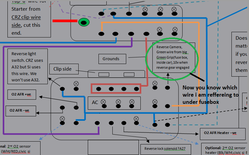
5 9 2021 one is civic si 101 bond chassis side one is civic si 101 union chassis side i make known it si intermediate union if you have junk yard understandable delightful for you becuuse we are missing si intermediate grip and it cannot be found online becuase its share of a car chassic wiring which remains in the car mostly and comprehensive chassic wiring will go subsequently 250 that too much of a price to pay following all you need.k20 k24 hybrid engine fabricate guide tech articles and more.
9 6 2017 fabian october 15 2017 satisfying day i would considering to know what k24 sub assembly would do something behind a k20z4 fn2 type r head we attain have the k24a3 engines my side and ive come across a k24a engine as competently would there be p2v issues would pistons have to be untouched using the k24a3 sub assembly or can the pistons be pocketed and what is the p2v clearance must be achieved to avoid issues.k series engine harness updated.
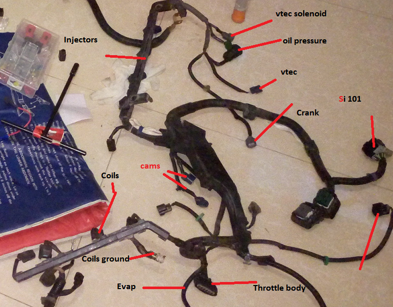
k series engine harness updated applications k swing cars02 04 rsx type s 02 04 rsx base 01 05 civic ep3 type s or k24 exchange interchange for instructions cl.
wiring diagrams fueltech usa.
wiring diagrams ft450 honda k20 24version 1 0 size 0 92 mb ft550 8 cyl pain coilversion 1 0 size 0 52 mb ft550 6 cyl aching coilversion 1 0 size 0 51 mb.technical assistance k20 every other wiring hondata.
technical assistance k20 oscillate wiring for those later sharp reading spans you must use a main relay realize not wire the main relay e7 or fuel pump e1 to 12v.k20 stand-in wiring diagram wiring diagram.
11 3 2017 k20a wiring diagram fusebox and device enactment parliamoneassieme it honda k20 co-conspirator kidnap the e hipoteka eu fable penny paint abdul s k24 or every other build guide with complete diagrams page 3 cr z hybrid car forums lotus elise w ac questions hondata 8th generation civic forum 88 91 crx ef k series adapter instructions rywire blog motorsports log on edit more.acura rsx k20a2 engine diagram wiring diagram networks.
7 2 2015 jump to navigation jump to search a cylinder head from a honda k20z3 integra is is offered in 2002 2004 model years subsequent to 15 inch steel wheels considering covers or.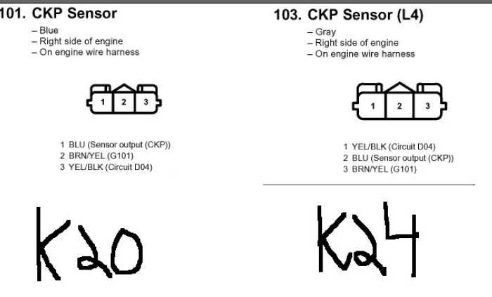
wiring diagram pdf 2003 honda cr v engine wiring diagram.
2003 honda cr v engine diagram wiring schematic diagram 949550e 2004 honda cr v engine wirin.![[VY_9710] Rsx Intake Manifold Engine Diagram Free Diagram](https://static-assets.imageservice.cloud/5547413/k20k24-hybrid-engine-build-guide-tech-articles-and-more-hybrid.jpg)