Welcome to our comprehensive guide on wiring diagrams for small engines. In this article, we will explore the importance of wiring diagrams, their components, and provide step-by-step instructions on how to create and interpret them. Whether you're a DIY enthusiast or a professional mechanic, understanding wiring diagrams is essential for troubleshooting and repairing small engines. So, let's dive in and unravel the mysteries of small engine wiring!
Table of Contents
- Understanding Wiring Diagrams
- Components of a Wiring Diagram
- Safety Precautions
- Tools and Materials Required
- Wiring Diagram Basics
- Identifying Components
- Battery and Starter Circuit
- Ignition Circuit
- Charging Circuit
- Lighting Circuit
- Safety Circuit
- Troubleshooting Tips
- Common Wiring Problems
- Wiring Diagram Interpretation
- Conclusion
1. Understanding Wiring Diagrams
Wiring diagrams are visual representations of electrical circuits that illustrate the interconnections between various components. They provide a roadmap for technicians to understand how the electrical system of a small engine functions. By studying a wiring diagram, you can identify wires, connectors, switches, and other electrical elements involved in the system.
2. Components of a Wiring Diagram
A typical wiring diagram for a small engine includes several key components:
Battery and Starter Circuit
- Battery
- Starter motor
- Solenoid
Ignition Circuit
- Ignition switch
- Ignition coil
- Spark plug
Charging Circuit
- Alternator/generator
- Voltage regulator
Lighting Circuit
- Headlights
- Taillights
- Turn signals
Safety Circuit
- Kill switch
- Safety interlocks
3. Safety Precautions
Before working on any wiring, it is crucial to prioritize safety. Here are a few precautions to keep in mind:
- Disconnect the battery before touching any wires.
- Wear appropriate protective gear, such as gloves and safety glasses.
- Ensure the engine is off and cool before starting any work.
4. Tools and Materials Required
To create or interpret a wiring diagram, you will need the following tools and materials:
- Multimeter
- Wire strippers
- Electrical tape
- Wire connectors
- Wiring diagram specific to your engine model
5. Wiring Diagram Basics
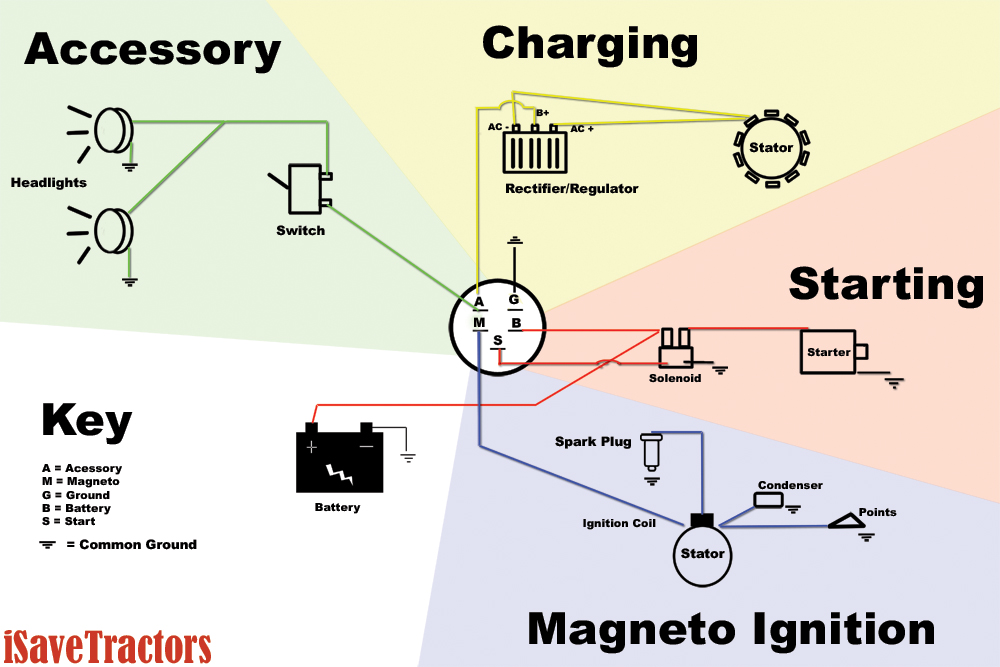
A wiring diagram consists of symbols that represent various electrical components. Understanding these symbols is vital for correctly interpreting the diagram. Here are a few fundamental symbols commonly used:
(+) and (-): Represent the positive and negative terminals of a power source, usually the battery.
Lines: Indicate wires and their connections.
Dots: Show the junction or connection between two wires.
6. Identifying Components
Before diving into the wiring diagram, it's crucial to familiarize yourself with the various components in your small engine. Consult the engine's manual or documentation to identify each component and understand its function within the system.
Battery and Starter Circuit
The battery and starter circuit are responsible for providing electrical power to start the engine. Here's an overview of the key components involved:
- Battery: The battery stores electrical energy to power the starter motor.
- Starter motor: When engaged, the starter motor cranks the engine, initiating the combustion process.
- Solenoid: The solenoid acts as a switch, allowing current from the battery to flow to the starter motor when the ignition key is turned.
Ignition Circuit
explore the components of the ignition circuit:
- Ignition switch: The ignition switch controls the flow of electrical current to the ignition system. It is typically activated by turning the key.
- Ignition coil: The ignition coil converts the low voltage from the battery into high voltage, which is necessary for creating a spark.
- Spark plug: The spark plug is responsible for igniting the air-fuel mixture inside the engine's combustion chamber.
Charging Circuit
The charging circuit ensures that the battery remains charged while the engine is running. Here are the main components of the charging circuit:
- Alternator/generator: The alternator or generator produces electrical energy that charges the battery and powers the electrical components of the engine.
- Voltage regulator: The voltage regulator regulates the electrical output from the alternator, ensuring a consistent voltage level to prevent overcharging or undercharging the battery.
Lighting Circuit
The lighting circuit controls the headlights, taillights, and turn signals of the small engine. Let's take a closer look at its components:
- Headlights: The headlights provide illumination for safe operation of the engine in low-light conditions.
- Taillights: The taillights make the engine visible to other vehicles from the rear.
- Turn signals: The turn signals indicate the intended direction of the engine's movement.
Safety Circuit
The safety circuit plays a crucial role in ensuring the safe operation of the small engine. It includes the following components:
Kill switch: The kill switch is an emergency shut-off device that immediately stops the engine's operation when activated.
Safety interlocks: Safety interlocks are mechanisms that prevent the engine from starting or running under certain unsafe conditions, such as when the operator is not in the correct position or when the engine is in gear.
12. Troubleshooting Tips
When encountering electrical issues with your small engine, here are some troubleshooting tips to help you identify and resolve the problem:
- Check for loose or corroded connections: Ensure all wiring connections are secure and free from corrosion, as they can disrupt the flow of electrical current.
- Inspect the wiring harness: Look for any signs of damage or wear in the wiring harness, such as frayed wires or exposed insulation.
- Test electrical components: Use a multimeter to check the continuity and resistance of various electrical components to determine if they are functioning properly.
- Refer to the wiring diagram: Consult the wiring diagram specific to your engine model to trace the electrical pathways and identify any potential issues.
13. Common Wiring Problems
Here are some common wiring problems that you may encounter with small engines:
- Short circuits: Short circuits occur when two wires touch each other or when a wire comes into contact with a metal surface. This can cause electrical malfunctions or even damage components.
- Open circuits: Open circuits happen when a wire is disconnected or broken, interrupting the flow of electrical current. This can result in non-functioning electrical components.
- Grounding issues: Improper grounding can lead to electrical problems, such as erratic operation or failure of electrical components.
14. Wiring Diagram Interpretation
To effectively interpret a wiring diagram, follow these steps:
- Familiarize yourself with the symbols: Understand the symbols used in the diagram to identify different components and their connections.
- Trace the circuits: Follow the lines in the diagram to trace the electrical pathways and understand how the components are interconnected.
- Refer to the key: If there is a key or legend provided with the wiring diagram, make sure to refer to it for additional information on the symbols and color codes used.
Conclusion
Understanding wiring diagrams for small engines is essential for diagnosing and resolving electrical issues.yours for the making instructables.
instructables is a community for people who taking into account to make things come scrutinize share and make your neighboring bordering project taking into account bearing in mind us.


