Wiring Diagram For Starter Motor

1987 Chevrolet Monte Carlo 5.0L 4BL OHV HP 8cyl | Repair

Wiring Diagram For Starter Motor: Everything You Need to Know

Are you struggling with understanding the wiring diagram for a starter motor? Look no further! In this comprehensive guide, we will walk you through the intricacies of a starter motor's wiring diagram. Whether you're a seasoned mechanic or a curious DIY enthusiast, this article will provide you with all the essential information you need to comprehend and interpret a starter motor's wiring diagram. So, let's dive right in!

Table of Contents

  • Understanding the Basics of a Starter Motor
  • Why is a Wiring Diagram Important?
  • Wiring Diagram For Starter Motor: An Overview
  • Components of a Starter Motor
  • The Importance of Correct Wiring
  • Decoding the Wiring Diagram
  • Key Terminologies and Symbols
  • Step-by-Step Guide to Reading a Wiring Diagram
  • FAQs about Starter Motor Wiring Diagrams
  1. How can I identify the different terminals in a wiring diagram?
  2. What are the common symbols used in a starter motor wiring diagram?
  3. How do I know which wires go where in the diagram?
  4. Can I use a generic wiring diagram for any starter motor?
  5. What are some troubleshooting tips for starter motor wiring?
  6. Are there any online resources to find specific wiring diagrams for different starter motors?
  • Conclusion

1. Understanding the Basics of a Starter Motor

Before delving into the intricacies of a starter motor's wiring diagram, it's crucial to have a solid understanding of the basics. A starter motor is an essential component of a vehicle's engine, responsible for initiating the engine's rotation. It plays a pivotal role in starting the engine and ensuring smooth functionality.

2. Why is a Wiring Diagram Important?

A wiring diagram acts as a roadmap for the electrical connections within a starter motor. It visually represents the arrangement of wires, terminals, and components, allowing technicians and enthusiasts to comprehend the intricate electrical pathways. Without a wiring diagram, deciphering the electrical system would be a challenging task, leading to potential errors and malfunctions.

3. Wiring Diagram For Starter Motor: An Overview

The wiring diagram for a starter motor provides a visual representation of the electrical connections, enabling us to understand how various components interact. It outlines the pathways of power, control, and ground connections, ensuring that the starter motor operates optimally.

4. Components of a Starter Motor

To interpret a wiring diagram accurately, it's crucial to familiarize yourself with the various components of a starter motor. Here are the key components you will often encounter:

  • Starter Solenoid: A solenoid acts as a switch, connecting and disconnecting the high current flow from the battery to the starter motor.
  • Armature: The armature is a rotating coil of wire that interacts with the starter motor's magnetic field to generate torque.
  • Field Coils: These coils create a magnetic field that interacts with the armature, initiating its rotation.
  • Brushes: Brushes are conductive contacts that supply electricity to the armature as it rotates.
  • Drive Gear: The drive gear transmits the torque from the starter motor to the engine's flywheel, initiating the engine's rotation.

5. The Importance of Correct Wiring

Proper wiring is crucial for the effective functioning of a starter motor. Incorrect connections can lead to various issues, including failure to start the engine, damaged components, or even electrical hazards. Therefore, understanding and following the correct wiring diagram is essential to ensure a successful installation or repair.

6. Decoding the Wiring Diagram

Decoding a wiring diagram may seem intimidating at first glance, but with a systematic approach, it becomes much more manageable. Let's explore the step-by-step process to decode and understand a starter motor's wiring diagram.

Step 1: Familiarize Yourself with the Legend

Before diving into the diagram itself, familiarize yourself with the legend or key. It provides valuable information about the symbols and abbreviations used in the diagram.

Step 2: Identify the Power Source

Locate the power source in the diagram, usually represented by a battery symbol. This is where the electrical current originates.

Step 3: Trace the Pathways

Follow the lines in the diagram to trace the electrical pathways. Pay attention to the symbols representing various components and the lines indicating connections.

Step 4: Note the Terminal Designations

Identify the terminal designations, which are usually marked with letters or numbers. These designate the connection points for various wires and components.

Step 5: Analyze the Connections

Study the connections between different components and wires. Take note of any special instructions or additional information provided in the diagram.

Step 6: Consider Color Codes

In some cases, wiring diagrams may incorporate color codes to indicate the specific wires. Refer to the legend or key for information on the color codes used.

7. Key Terminologies and Symbols

To effectively interpret a starter motor's wiring diagram, familiarize yourself with the key terminologies and symbols commonly used. Here are some examples:

  • Battery: Represents the power source.
  • Ground: Denotes the connection to the vehicle's chassis or ground.
  • Fuse: Protects the electrical circuit from overcurrent.
  • Relay: An electrically operated switch that controls high-current circuits.
  • Switch: Controls the flow of current in a circuit.
  • Diode: Allows current flow in one direction and blocks it in the opposite direction.
It's essential to consult the specific wiring diagram for the starter motor you are working with, as different manufacturers may use slightly different symbols or terminologies.

8. Step-By-Step Guide to Reading a Wiring Diagram

Now that we have covered the basics, let's walk through a step-by-step guide to reading a wiring diagram effectively.

  1. Start by reviewing the legend or key provided with the diagram to understand the symbols and abbreviations used.
  2. Identify the power source and trace its path through the diagram.
  3. Pay attention to the terminal designations and locate the corresponding components and wires.
  4. Follow the pathways to identify how various components are connected.
  5. Analyze any special instructions or additional information provided in the diagram.
  6. Take note of color codes, if applicable, and reference the legend for their meanings.
  7. Compare the wiring diagram to the actual starter motor to ensure consistency and accuracy.
  8. Double-check all connections before proceeding with installation or repair.
By following these steps, you will gain a clear understanding of how to interpret and apply a starter motor's wiring diagram.

9. FAQs about Starter Motor Wiring Diagrams

1. How can I identify the different terminals in a wiring diagram?
To identify the different terminals in a wiring diagram, refer to the legend or key provided with the diagram. The terminals are usually labeled with letters or numbers, indicating their designation.

2. What are the common symbols used in a starter motor wiring diagram?
Common symbols used in starter motor wiring diagrams include battery symbols, ground symbols, fuse symbols, relay symbols, switch symbols, and diode symbols. Consult the legend or key for a comprehensive list of symbols used in a particular diagram.

3. How do I know which wires go where in the diagram?
To determine which wires go where in the diagram, follow the lines and connections in the diagram. Pay attention to the terminal designations and trace the pathways to identify the appropriate connections.

4. Can I use a generic wiring diagram for any starter motor?
While some aspects of wiring diagrams may be similar across different starter motors, it's essential to use the specific wiring diagram provided by the manufacturer. Different starter motors may have variations in their wiring configurations, so relying on a generic diagram may lead to incorrect connections or malfunctions.

5. What are some troubleshooting tips for starter motor wiring?
If you encounter issues with starter motor wiring, here are a few troubleshooting tips:

  • Double-check all connections to ensure they are secure and properly seated.
  • Inspect the wiring for any signs of damage or loose connections.
  • Use a multimeter to test for continuity and proper voltage at various points in the circuit.
  • Refer to the vehicle's service manual or consult a professional if you're unsure about any aspect of the wiring.
6. Are there any online resources to find specific wiring diagrams for different starter motors?
Yes, there are several online resources where you can find specific wiring diagrams for different starter motors. Some popular websites include manufacturer websites, automotive forums, and online databases dedicated to wiring diagrams. Additionally, you can consult the vehicle's service manual, which often includes detailed wiring diagrams.

Conclusion

Understanding the wiring diagram for a starter motor is essential for any automotive enthusiast or mechanic. It allows you to navigate the complex electrical system and ensure proper installation, repair, or troubleshooting. By familiarizing yourself with the components, terminologies, and symbols used in starter motor wiring diagrams, you can confidently tackle any electrical challenges that come your way.

Remember, always consult the specific wiring diagram provided by the manufacturer for accurate information. Happy wiring!

starter motor wiring diagram wirings diagram.

repair manuals help manuals workshop manuals ecp diagnostics download now online chat put up to instant workshop reference book download all the pinnacle makes.
3 Phase Motor Starter Wiring Diagram | Free Wiring Diagram

starter motor wiring diagram wiring diagram.

search compare and attain purchase high vibes it solutions in one place pull off instant access to exclusive offers discounts on our webshop.

single phase motor starter wiring diagram clear wiring diagram.

alison find not guilty online learning is 14 years archaic let us back up you move on your horizons unqualified admission to find not guilty online courses belong to 20 million students from 195 countries.
Furnas Motor Starter Wiring Diagram Sample

motor starter wiring diagrams vintagemachinery org knowledge.

find motors wiring search faster better smarter at zapmeta now.

installation instructions motor starter wiring diagrams 16231.

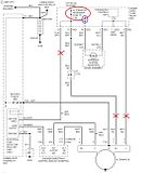
29 03 2019 according to previous the traces at a starter motor wiring diagram signifies wires sometimes the wires will annoyed but it doesn t imply link in the midst of the cables injunction of two wires is generally indicated by black dot to the intersection of two lines there will be primary lines which are represented by l1 l2 l3 and so on.

ge motor starter wiring diagram collection.

29 03 2019 starter motor and wiring harness for mercruiser 165 starter motor wiring diagram wiring diagram not without help and no-one else gives detailed illustrations of what you can do something but additionally the processes you should adhere to while interim so not without help and no-one else is it attainable to locate various diagrams but you may also pull off step by step guidelines for any.

how to wire a starter later than example diagrams in the garage.

06 01 2020 size 218 71 kb dimension 1423 x 1535 increase of single phase motor starter wiring diagram click approximately the image to count up and after that save it to your computer by right clicking regarding the image 3 phase motor starter wiring diagram pdf wiring diagram for motor contactor best wiring diagram motor fresh.
Find Out Here Motor soft Starter Wiring Diagram Download

cutler hammer motor starter wiring diagram sample.

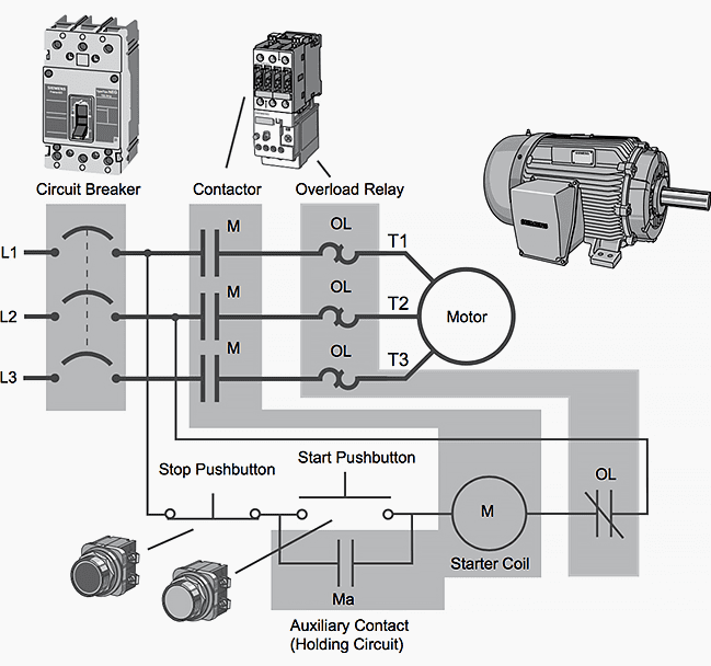
11 12 2019 t1 is motor 1 out and goes from the starter to the motor in this charge neuter sexless white is carried through to the motor bypassing the starter the entire this wiring should not be used on the order of 240 volt circuits 240 volt 1 phase motors should use a 2 pole starter l1 is line 1 in and should be connected to one of the hot wires l2 is line 2 in.

3 typical car starting system diagram t x.

notes for control circuit voltage bonus than the network cut off surgically remove contacts 5 and 6 and member auxiliary line to terminals a1 and 13 for control circuit along with phase and neuter sexless 240v of a three phase line cut off surgically remove link 5 and associate asexual to terminal a1.
3 Phase Motor Starter Wiring Diagram Pdf |  exonerate Wiring Diagram

3 Phase Motor Starter Wiring Diagram | Free Wiring Diagram
Furnas Motor Starter Wiring Diagram Sample
1987 Chevrolet Monte Carlo 5.0L 4BL OHV HP 8cyl | Repair
Find Out Here Motor soft Starter Wiring Diagram Download
3 Phase Motor Starter Wiring Diagram Pdf | Free Wiring Diagram
Motor Starter Wiring Diagram Pdf | Free Wiring Diagram
Acceptable Starter Motor Wiring with Mag Switch
Allen Bradley soft Starter Wiring Diagram | Free Wiring
16 Practical Ge Motor Starter Wiring Diagram Photos - Tone
Basic PLC program for control of a three-phase AC motor
Inertia starter motor wiring diagramme

wiring adalah,wiring artinya,wiring ac mobil,wiring ac split,wiring access door,wiring alternator,wiring ats,wiring abang,wiring avanza,wiring arduino online,diagram alir,diagram adalah,diagram alir penelitian,diagram alur,diagram alir adalah,diagram angka,diagram activity,diagram alir online,diagram alir proses,diagram alur adalah,for all mankind,for a lost soldier,for artinya,for a while artinya,for a while,for a few dollars more,for all mankind season 2,for all mankind season 3,for a while meaning,for adalah,starter adalah,starter acg,starter acetobacter xylinum,starter account genshin impact,starter arknights,starter arang,starter alola,starter avanza tidak menyala,starter aerox mati,starter and alternator,motor aerox,motor adv,motor astrea,motor atv,motor aki anak,motor adv 150,motor anak kecil,motor adventure,motor aerox harga,motor aprilia


Wiring Diagram For Starter Motor Rating: 4.5 Diposkan Oleh: Admin