“RV solar wiring diagram with battery and inverter”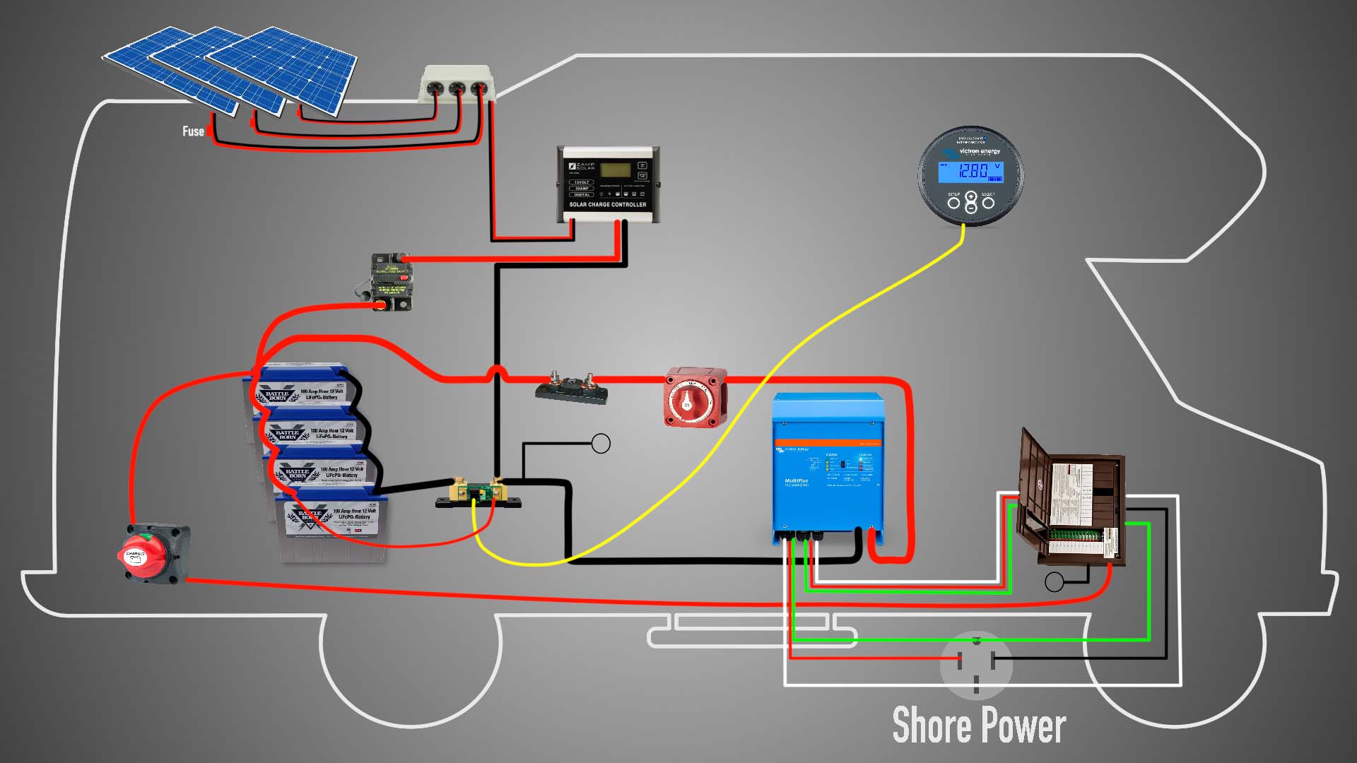
Design Considerations for RV Solar Wiring Diagram
When designing an RV solar wiring diagram, the following considerations should be taken into account:
- Voltage and Current Ratings: The diagram should ensure that the voltage and current ratings of each component are compatible with each other, and that the overall system is safe and efficient.
- Wire Sizing and Insulation: The diagram should specify the correct wire size and insulation for each connection, to prevent overheating, voltage drop, and electrical shock.
- Grounding and Bonding: The diagram should show the grounding and bonding connections for each component, to ensure electrical safety and prevent corrosion.
- Overcurrent Protection: The diagram should include overcurrent protection devices such as fuses or circuit breakers, to prevent electrical fires and damage to components.
- System Monitoring and Control: The diagram should show the system monitoring and control devices, such as voltage and current meters, and remote monitoring systems.
Best Practices for RV Solar Wiring Diagram

To ensure a safe, efficient, and reliable RV solar power system, the following best practices should be followed:
- Use Standardized Components and Connectors: Use standardized components and connectors to ensure compatibility and ease of maintenance.
- Follow Manufacturer’s Instructions: Follow the manufacturer’s instructions for each component, to ensure proper installation, configuration, and operation.
- Use Color-Coded Wiring: Use color-coded wiring to identify different voltage and current levels, and to prevent misconnection.
- Label and Document the System: Label and document the system, to facilitate maintenance, troubleshooting, and upgrades.
- Test and Validate the System: Test and validate the system, to ensure that it operates safely and efficiently.

Example RV Solar Wiring Diagram
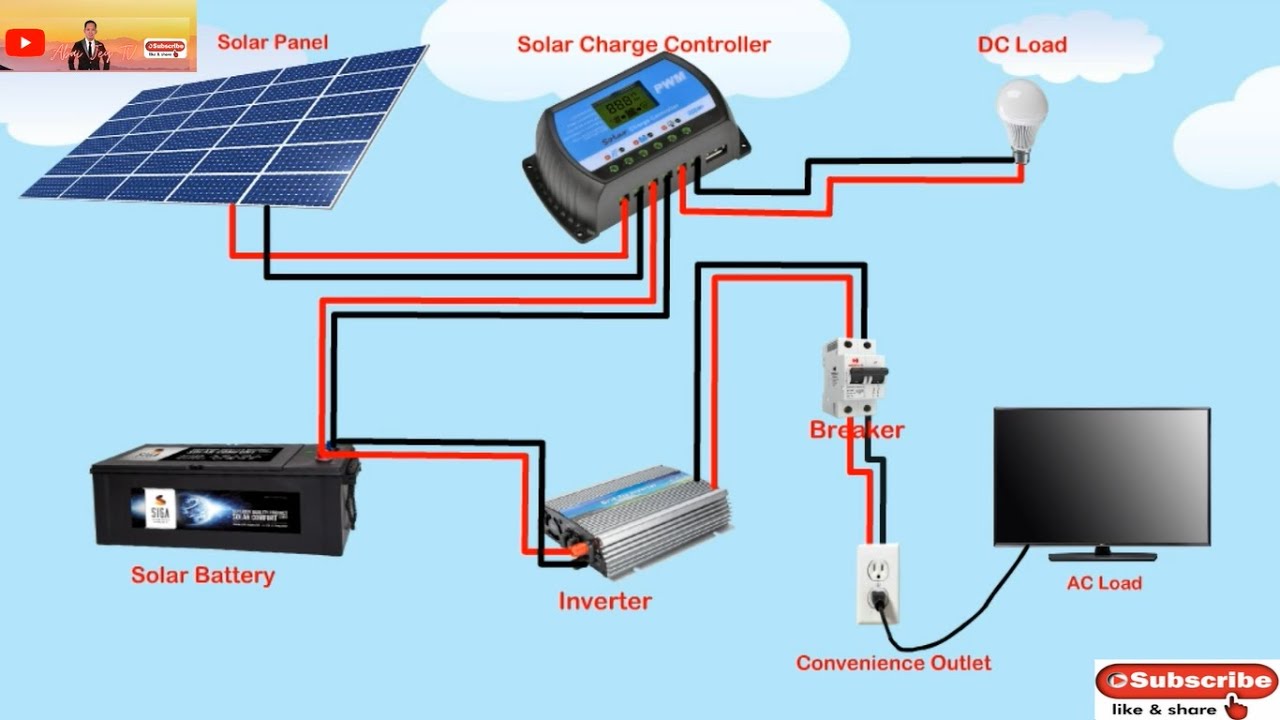
The following is an example of a comprehensive RV solar wiring diagram with battery and inverter:
- Solar Panels (4 x 300W, 12V)
- Connected to Charge Controller (40A, 12V)
- Charge Controller connected to Battery Bank (4 x 200Ah, 12V)
- Battery Bank connected to Inverter/Charger (2000W, 12V)
- Inverter/Charger connected to Appliance Panel (120V, 20A)
- Appliance Panel
- Connected to Refrigerator (120V, 10A)
- Connected to Air Conditioner (120V, 15A)
- Connected to Lights and Outlets (120V, 5A)
- Grounding and Bonding
- Solar Panels grounded to chassis
- Charge Controller grounded to chassis
- Battery Bank grounded to chassis
- Inverter/Charger grounded to chassis
- Appliance Panel grounded to chassis
- Overcurrent Protection
- Fuses (20A, 30A) installed in series with each appliance
- Circuit Breaker (40A) installed in series with Inverter/Charger
- System Monitoring and Control
- Voltage and Current Meters installed on Charge Controller and Inverter/Charger
- Remote Monitoring System installed to monitor system performance and receive alerts
Conclusion
A comprehensive RV solar wiring diagram with battery and inverter is crucial to ensure a safe, efficient, and reliable electrical system. By following the design considerations, best practices, and example diagram outlined in this article, RV owners can create a well-designed solar power system that meets their energy needs while on the move. Remember to always follow manufacturer’s instructions, use standardized components and connectors, and label and document the system to facilitate maintenance, troubleshooting, and upgrades. With a well-designed RV solar power system, you can enjoy the freedom and convenience of solar-powered adventures, while minimizing your environmental impact.