These systems allow homeowners and businesses to generate their own electricity, reducing their reliance on the grid and minimizing their carbon footprint. However, designing and installing an off-grid solar panel system can be complex, requiring careful planning and attention to detail. One crucial aspect of off-grid solar panel systems is the wiring diagram, which connects the solar panels to the inverter. In this article, we will provide a comprehensive guide to creating a wiring diagram for an off-grid solar panel to inverter.
Understanding the Components
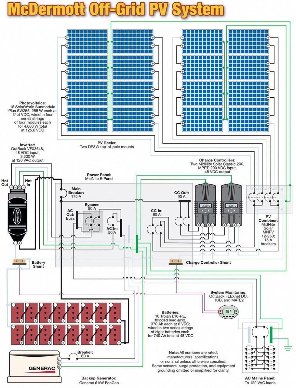
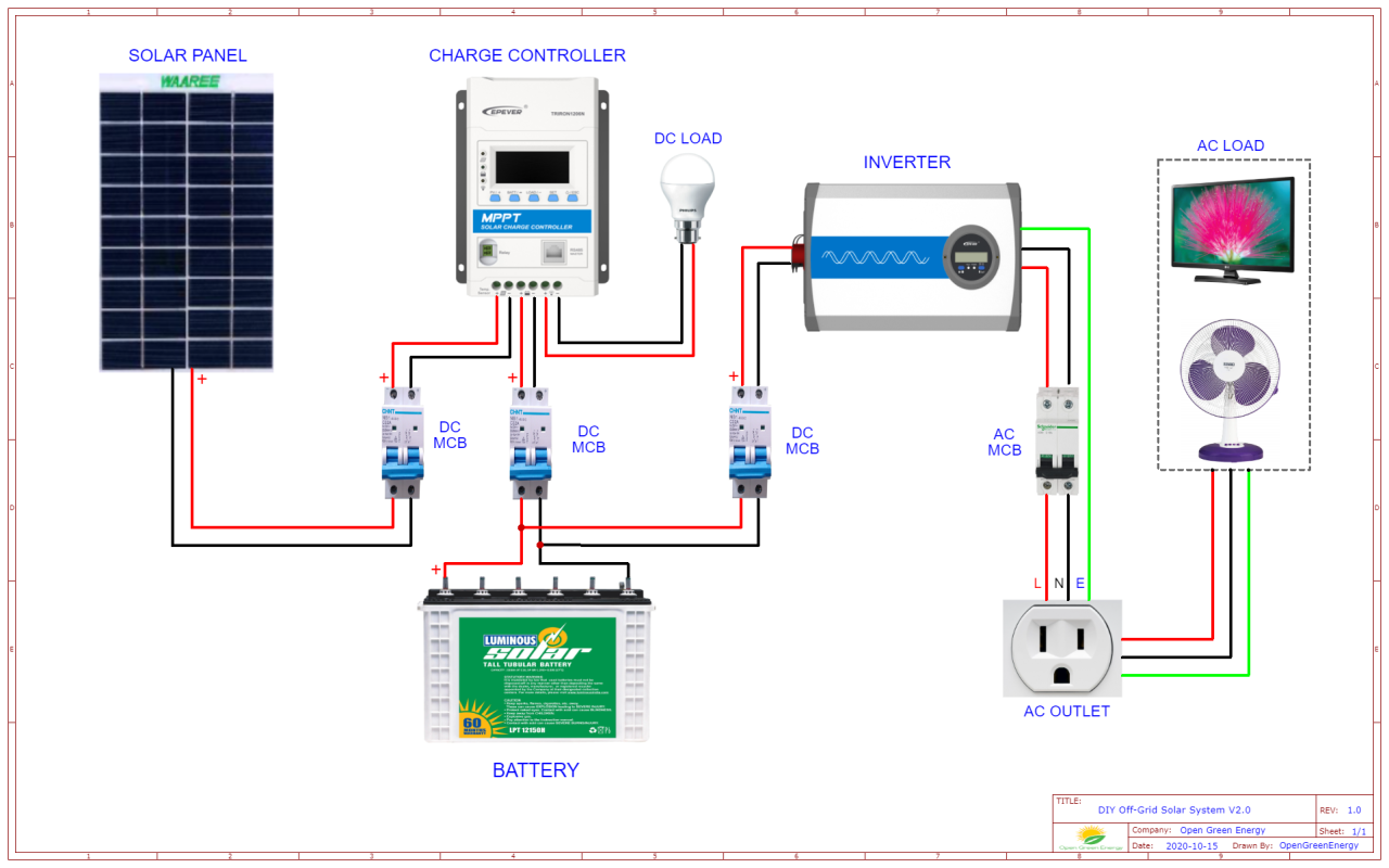
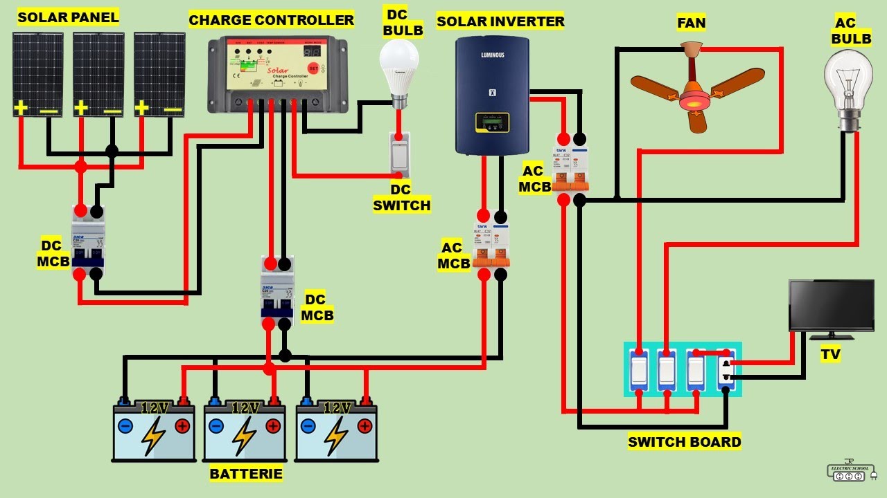
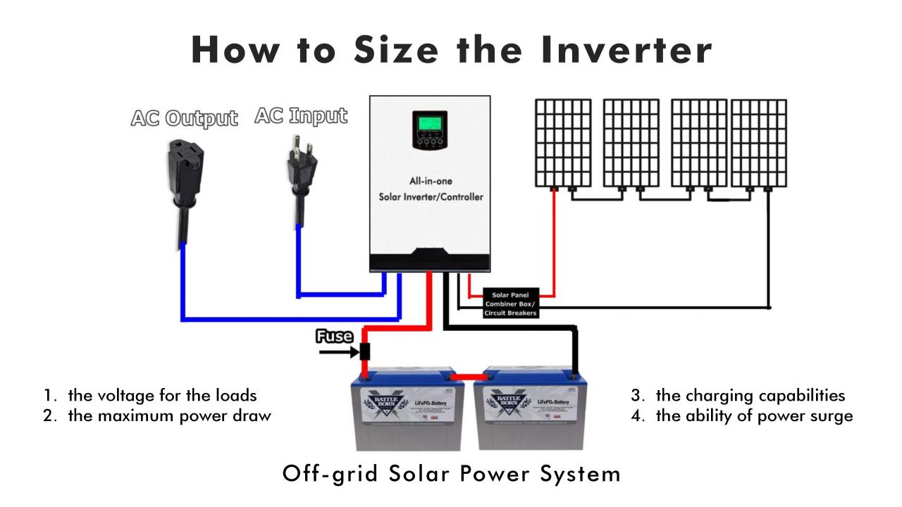
Before diving into the wiring diagram, it's essential to understand the components involved in an off-grid solar panel system. These include:
- Solar Panels: These are the photovoltaic (PV) panels that convert sunlight into direct current (DC) electricity.
- Charge Controller: This device regulates the flow of energy from the solar panels to the battery bank, preventing overcharging and ensuring the batteries are charged efficiently.
- Battery Bank: This is the storage system for the excess energy generated by the solar panels. The battery bank provides power to the inverter during periods of low sunlight or at night.
- Inverter: This device converts the DC electricity from the battery bank into alternating current (AC) electricity, which is usable by household appliances.
- Load Center: This is the main electrical panel that distributes power to the various loads in the system, such as lights, appliances, and outlets.
Wiring Diagram Components
A wiring diagram for an off-grid solar panel to inverter consists of several key components, including:
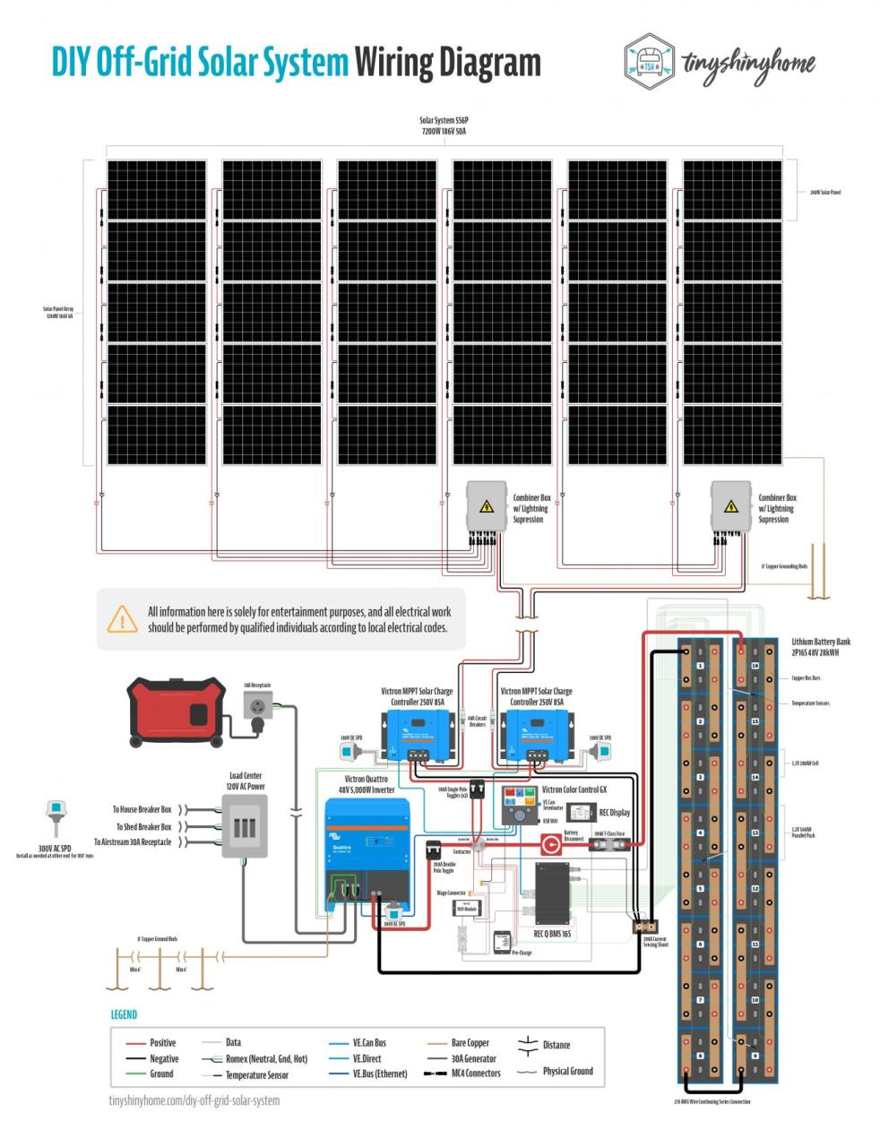
- Solar Panel Array: This is the collection of solar panels connected in series and parallel to form a single unit.
- Charge Controller Input: This is the connection point for the solar panel array to the charge controller.
- Charge Controller Output: This is the connection point for the charge controller to the battery bank.
- Battery Bank: This is the connection point for the charge controller output to the battery bank.
- Inverter Input: This is the connection point for the battery bank to the inverter.
- Inverter Output: This is the connection point for the inverter to the load center.
- Grounding System: This is the connection point for the entire system to the earth, providing a safe path for electrical current to flow to ground in the event of a fault.
Creating a Wiring Diagram
To create a wiring diagram for an off-grid solar panel to inverter, follow these steps:
- Determine the System Size: Calculate the total wattage required by the load center and the number of solar panels needed to meet that demand.
- Choose the Components: Select the charge controller, battery bank, and inverter based on the system size and requirements.
- Determine the Wire Size: Calculate the wire size required for each connection point based on the ampacity and voltage of the system.
- Create the Diagram: Use a diagramming software or draw the wiring diagram by hand, including all the components and connection points.
- Label the Components: Label each component and connection point clearly, including the wire size and color.
Example Wiring Diagram
Here is an example wiring diagram for an off-grid solar panel to inverter:
Solar Panel Array
- 4 x 300W solar panels connected in series (1200W total)
- Connected to charge controller input
Charge Controller
- Input: 1200W solar panel array
- Output: 48V, 25A
Battery Bank
- 12 x 200Ah deep cycle batteries connected in series and parallel (2400Wh total)
- Connected to charge controller output
Inverter
- Input: 48V, 25A from battery bank
- Output: 120/240V, 5000W
Load Center
- Connected to inverter output
- Distributes power to various loads, such as lights, appliances, and outlets
Grounding System
- Connected to earth ground
- Provides a safe path for electrical current to flow to ground in the event of a fault
Best Practices
When creating a wiring diagram for an off-grid solar panel to inverter, follow these best practices:
- Use Proper Wire Size: Ensure the wire size is sufficient for the ampacity and voltage of the system.
- Use Color-Coded Wires: Use color-coded wires to identify the different connections and components.
- Label Components Clearly: Label each component and connection point clearly, including the wire size and color.
- Follow Safety Protocols: Follow safety protocols when working with electrical systems, including wearing protective gear and ensuring the system is de-energized before performing maintenance.
- Test the System: Test the system thoroughly before putting it into operation, ensuring all components are functioning correctly and safely.
Conclusion
Creating a wiring diagram for an off-grid solar panel to inverter requires careful planning and attention to detail. By understanding the components involved and following best practices, you can design a safe and efficient system that meets your energy needs. Remember to test the system thoroughly before putting it into operation and follow safety protocols when working with electrical systems. With a properly designed and installed off-grid solar panel system, you can enjoy the benefits of renewable energy and reduce your reliance on the grid.
Additional Resources
For more information on wiring diagrams and off-grid solar panel systems, refer to the following resources:
- National Electric Code (NEC)
- International Association of Electrical Inspectors (IAEI)
- Solar Energy Industries Association (SEIA)
- National Renewable Energy Laboratory (NREL)
By following the guidelines and best practices outlined in this article, you can create a safe and efficient wiring diagram for your off-grid solar panel to inverter, ensuring a reliable and sustainable source of energy for your home or business.