circuit diagram of ac voltmeter

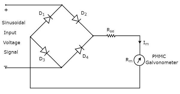
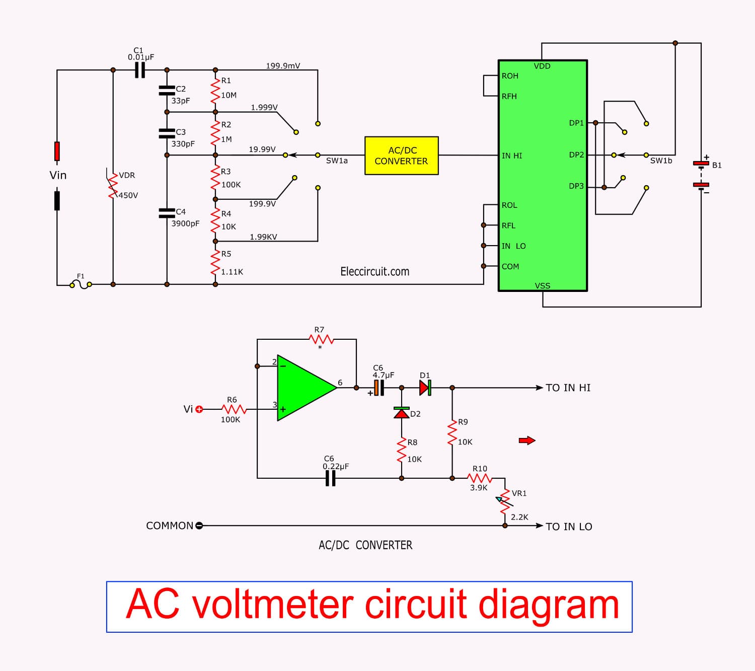

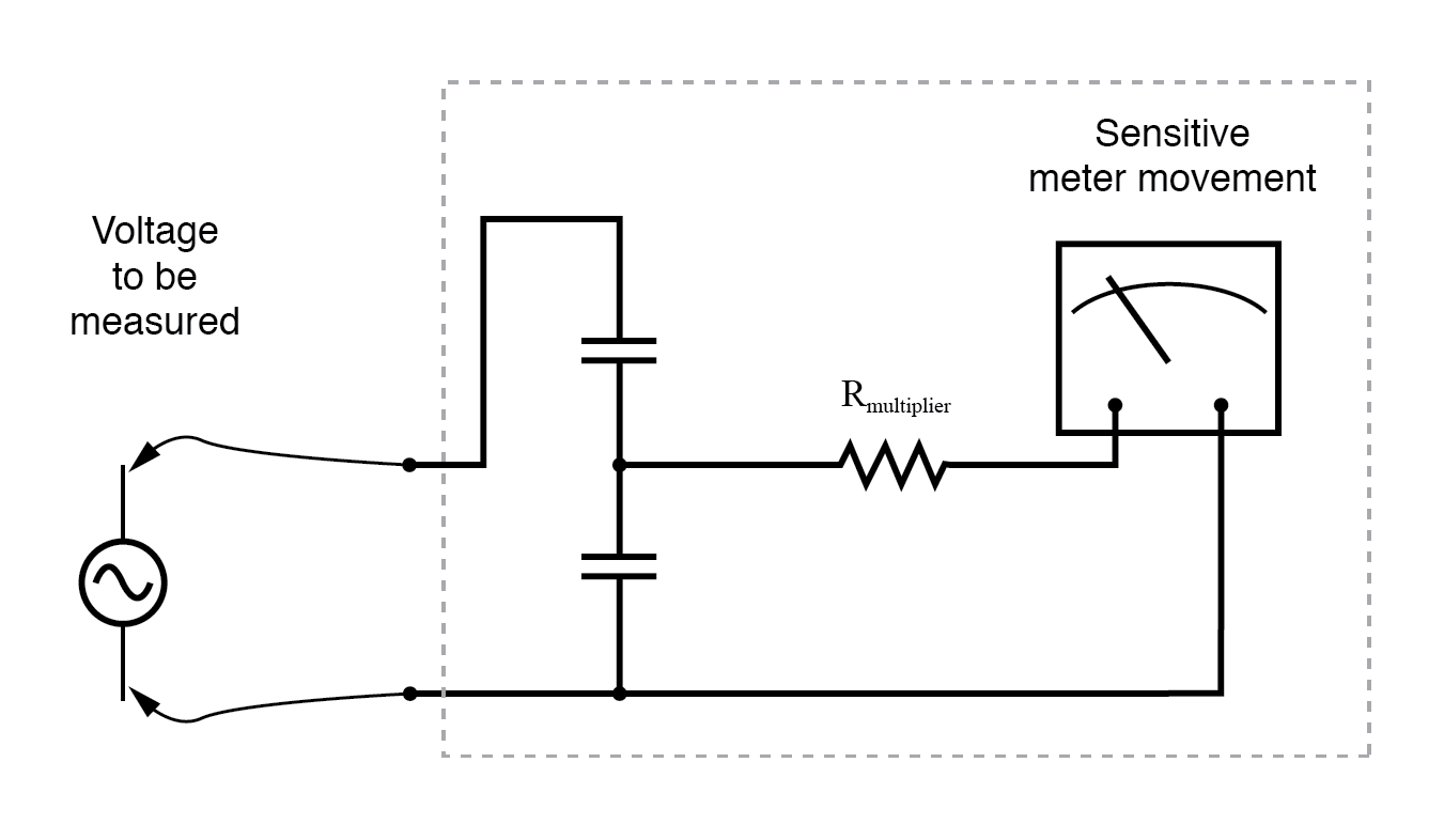


p arduino ac voltmeter project with code and circuit diagram 20 08 2017 making a digital voltmeter is a lot easy than making an analog one because in case of analog voltmeter you must have good knowledge of physical parameters like torque friction losses etc whereas in case of digital voltmeter you can just use a lcd or led matrix or even your laptop as in this case to print the voltage values for you p p ac voltmeters electronic circuits and diagrams electronic 23 09 2009 ac voltmeter block diagram broadly ac voltmeters can be divided into three categories 1 average reading ac voltmeters ac voltmeter using vacuum tube diode normally ac voltmeters are average responding type and the meter is calibrated in terms of the rms values for a sine wave ac voltmeters tutorialspoint the above block diagram consists of two blocks half wave rectifier and dc voltmeter we will get the corresponding circuit diagram just by replacing each block with the respective component s in above block diagram so the circuit diagram of ac voltmeter using half wave rectifier will look like as shown in below figure the rms value of circuit diagram of ac voltmeter hasil pencarian gambar block diagram of ac voltmeter to develop a basic understanding of ac voltmeter it is crucial to have a brief idea of the block diagram of ac voltmeter circuit the block diagram of ac voltmeter resembles the block diagram of dc voltmeter except the fact that rectifier is used in case of ac voltmeter what is ac voltmeter average reading peak reading and true 16 05 2019 figure 5 the simple dc digital meter circuit is completely in figure 5 is the digital voltmeter circuit designed for general applications which it requires the maximum range equal to 200mv if you want more the voltage range which they can do the circuit for reducing the voltage the circuit consists of rx ry calculated as follows digital voltmeter circuit diagram using icl7107 7106 with pcb powerline voltmeter schematic circuit diagram here s a rather special voltmeter that will let you measure the ac grid voltage and also see very accurately how p p powerline voltmeter schematic circuit diagram 16 11 2019 the ac input is connected to the circuit as shown where diode 1n4007 is used to eliminate the negative half cycles after we get the positive parts of the ac voltage signal it enters to a voltage divider because the arduino uno board can t deal with voltages higher than 5v measure ac voltage with arduino ac voltmeter 13 08 2017 another circuit diagram of a direct coupled amplifier dc voltmeter using fet in input stage is shown in figure in this voltmeter voltage to be measured is firstly attenuated with range selector switch to keep the input voltage of amplifier within its level dc voltmeter circuit diagram block diagram basic guide 08 03 2019 why this ac voltmeter circuit is different if you go to google and search ac voltmeter using arduino you will find many circuits all over the internet but in almost all those circuits you will find a transformer being used transformerless ac voltmeter circuit using arduino homemade circuit diagram and working the internal circuit of lm3914 is shown in below figure as discussed the lm3914 is a 10 stage measuring unit this is shown in above internal circuit lm3914 is basically a combination of 10 comparators each comparator is an op amp with gaining reference voltage at its negative terminal lm3914 voltmeter circuit diagram p p ac voltmeter search ac voltmeter aux ac information circuit of voltmeter search circuit of voltmeter
p arduino ac voltmeter project with code and circuit diagram 20 08 2017 making a digital voltmeter is a lot easy than making an analog one because in case of analog voltmeter you must have good knowledge of physical parameters like torque friction losses etc whereas in case of digital voltmeter you can just use a lcd or led matrix or even your laptop as in this case to print the voltage values for you p p ac voltmeters electronic circuits and diagrams electronic 23 09 2009 ac voltmeter block diagram broadly ac voltmeters can be divided into three categories 1 average reading ac voltmeters ac voltmeter using vacuum tube diode normally ac voltmeters are average responding type and the meter is calibrated in terms of the rms values for a sine wave ac voltmeters tutorialspoint the above block diagram consists of two blocks half wave rectifier and dc voltmeter we will get the corresponding circuit diagram just by replacing each block with the respective component s in above block diagram so the circuit diagram of ac voltmeter using half wave rectifier will look like as shown in below figure the rms value of circuit diagram of ac voltmeter hasil pencarian gambar block diagram of ac voltmeter to develop a basic understanding of ac voltmeter it is crucial to have a brief idea of the block diagram of ac voltmeter circuit the block diagram of ac voltmeter resembles the block diagram of dc voltmeter except the fact that rectifier is used in case of ac voltmeter what is ac voltmeter average reading peak reading and true 16 05 2019 figure 5 the simple dc digital meter circuit is completely in figure 5 is the digital voltmeter circuit designed for general applications which it requires the maximum range equal to 200mv if you want more the voltage range which they can do the circuit for reducing the voltage the circuit consists of rx ry calculated as follows digital voltmeter circuit diagram using icl7107 7106 with pcb powerline voltmeter schematic circuit diagram here s a rather special voltmeter that will let you measure the ac grid voltage and also see very accurately how p p powerline voltmeter schematic circuit diagram 16 11 2019 the ac input is connected to the circuit as shown where diode 1n4007 is used to eliminate the negative half cycles after we get the positive parts of the ac voltage signal it enters to a voltage divider because the arduino uno board can t deal with voltages higher than 5v measure ac voltage with arduino ac voltmeter 13 08 2017 another circuit diagram of a direct coupled amplifier dc voltmeter using fet in input stage is shown in figure in this voltmeter voltage to be measured is firstly attenuated with range selector switch to keep the input voltage of amplifier within its level dc voltmeter circuit diagram block diagram basic guide 08 03 2019 why this ac voltmeter circuit is different if you go to google and search ac voltmeter using arduino you will find many circuits all over the internet but in almost all those circuits you will find a transformer being used transformerless ac voltmeter circuit using arduino homemade circuit diagram and working the internal circuit of lm3914 is shown in below figure as discussed the lm3914 is a 10 stage measuring unit this is shown in above internal circuit lm3914 is basically a combination of 10 comparators each comparator is an op amp with gaining reference voltage at its negative terminal lm3914 voltmeter circuit diagram p p ac voltmeter search ac voltmeter aux ac information circuit of voltmeter search circuit of voltmeter
p arduino ac voltmeter project with code and circuit diagram 20 08 2017 making a digital voltmeter is a lot easy than making an analog one because in case of analog voltmeter you must have good knowledge of physical parameters like torque friction losses etc whereas in case of digital voltmeter you can just use a lcd or led matrix or even your laptop as in this case to print the voltage values for you p p ac voltmeters electronic circuits and diagrams electronic 23 09 2009 ac voltmeter block diagram broadly ac voltmeters can be divided into three categories 1 average reading ac voltmeters ac voltmeter using vacuum tube diode normally ac voltmeters are average responding type and the meter is calibrated in terms of the rms values for a sine wave ac voltmeters tutorialspoint the above block diagram consists of two blocks half wave rectifier and dc voltmeter we will get the corresponding circuit diagram just by replacing each block with the respective component s in above block diagram so the circuit diagram of ac voltmeter using half wave rectifier will look like as shown in below figure the rms value of circuit diagram of ac voltmeter hasil pencarian gambar block diagram of ac voltmeter to develop a basic understanding of ac voltmeter it is crucial to have a brief idea of the block diagram of ac voltmeter circuit the block diagram of ac voltmeter resembles the block diagram of dc voltmeter except the fact that rectifier is used in case of ac voltmeter what is ac voltmeter average reading peak reading and true 16 05 2019 figure 5 the simple dc digital meter circuit is completely in figure 5 is the digital voltmeter circuit designed for general applications which it requires the maximum range equal to 200mv if you want more the voltage range which they can do the circuit for reducing the voltage the circuit consists of rx ry calculated as follows digital voltmeter circuit diagram using icl7107 7106 with pcb powerline voltmeter schematic circuit diagram here s a rather special voltmeter that will let you measure the ac grid voltage and also see very accurately how p p powerline voltmeter schematic circuit diagram 16 11 2019 the ac input is connected to the circuit as shown where diode 1n4007 is used to eliminate the negative half cycles after we get the positive parts of the ac voltage signal it enters to a voltage divider because the arduino uno board can t deal with voltages higher than 5v measure ac voltage with arduino ac voltmeter 13 08 2017 another circuit diagram of a direct coupled amplifier dc voltmeter using fet in input stage is shown in figure in this voltmeter voltage to be measured is firstly attenuated with range selector switch to keep the input voltage of amplifier within its level dc voltmeter circuit diagram block diagram basic guide 08 03 2019 why this ac voltmeter circuit is different if you go to google and search ac voltmeter using arduino you will find many circuits all over the internet but in almost all those circuits you will find a transformer being used transformerless ac voltmeter circuit using arduino homemade circuit diagram and working the internal circuit of lm3914 is shown in below figure as discussed the lm3914 is a 10 stage measuring unit this is shown in above internal circuit lm3914 is basically a combination of 10 comparators each comparator is an op amp with gaining reference voltage at its negative terminal lm3914 voltmeter circuit diagram p p ac voltmeter search ac voltmeter aux ac information circuit of voltmeter search circuit of voltmeter
p arduino ac voltmeter project with code and circuit diagram 20 08 2017 making a digital voltmeter is a lot easy than making an analog one because in case of analog voltmeter you must have good knowledge of physical parameters like torque friction losses etc whereas in case of digital voltmeter you can just use a lcd or led matrix or even your laptop as in this case to print the voltage values for you p p ac voltmeters electronic circuits and diagrams electronic 23 09 2009 ac voltmeter block diagram broadly ac voltmeters can be divided into three categories 1 average reading ac voltmeters ac voltmeter using vacuum tube diode normally ac voltmeters are average responding type and the meter is calibrated in terms of the rms values for a sine wave ac voltmeters tutorialspoint the above block diagram consists of two blocks half wave rectifier and dc voltmeter we will get the corresponding circuit diagram just by replacing each block with the respective component s in above block diagram so the circuit diagram of ac voltmeter using half wave rectifier will look like as shown in below figure the rms value of circuit diagram of ac voltmeter hasil pencarian gambar block diagram of ac voltmeter to develop a basic understanding of ac voltmeter it is crucial to have a brief idea of the block diagram of ac voltmeter circuit the block diagram of ac voltmeter resembles the block diagram of dc voltmeter except the fact that rectifier is used in case of ac voltmeter what is ac voltmeter average reading peak reading and true 16 05 2019 figure 5 the simple dc digital meter circuit is completely in figure 5 is the digital voltmeter circuit designed for general applications which it requires the maximum range equal to 200mv if you want more the voltage range which they can do the circuit for reducing the voltage the circuit consists of rx ry calculated as follows digital voltmeter circuit diagram using icl7107 7106 with pcb powerline voltmeter schematic circuit diagram here s a rather special voltmeter that will let you measure the ac grid voltage and also see very accurately how p p powerline voltmeter schematic circuit diagram 16 11 2019 the ac input is connected to the circuit as shown where diode 1n4007 is used to eliminate the negative half cycles after we get the positive parts of the ac voltage signal it enters to a voltage divider because the arduino uno board can t deal with voltages higher than 5v measure ac voltage with arduino ac voltmeter 13 08 2017 another circuit diagram of a direct coupled amplifier dc voltmeter using fet in input stage is shown in figure in this voltmeter voltage to be measured is firstly attenuated with range selector switch to keep the input voltage of amplifier within its level dc voltmeter circuit diagram block diagram basic guide 08 03 2019 why this ac voltmeter circuit is different if you go to google and search ac voltmeter using arduino you will find many circuits all over the internet but in almost all those circuits you will find a transformer being used transformerless ac voltmeter circuit using arduino homemade circuit diagram and working the internal circuit of lm3914 is shown in below figure as discussed the lm3914 is a 10 stage measuring unit this is shown in above internal circuit lm3914 is basically a combination of 10 comparators each comparator is an op amp with gaining reference voltage at its negative terminal lm3914 voltmeter circuit diagram p p ac voltmeter search ac voltmeter aux ac information circuit of voltmeter search circuit of voltmeter
p arduino ac voltmeter project with code and circuit diagram 20 08 2017 making a digital voltmeter is a lot easy than making an analog one because in case of analog voltmeter you must have good knowledge of physical parameters like torque friction losses etc whereas in case of digital voltmeter you can just use a lcd or led matrix or even your laptop as in this case to print the voltage values for you p p ac voltmeters electronic circuits and diagrams electronic 23 09 2009 ac voltmeter block diagram broadly ac voltmeters can be divided into three categories 1 average reading ac voltmeters ac voltmeter using vacuum tube diode normally ac voltmeters are average responding type and the meter is calibrated in terms of the rms values for a sine wave ac voltmeters tutorialspoint the above block diagram consists of two blocks half wave rectifier and dc voltmeter we will get the corresponding circuit diagram just by replacing each block with the respective component s in above block diagram so the circuit diagram of ac voltmeter using half wave rectifier will look like as shown in below figure the rms value of circuit diagram of ac voltmeter hasil pencarian gambar block diagram of ac voltmeter to develop a basic understanding of ac voltmeter it is crucial to have a brief idea of the block diagram of ac voltmeter circuit the block diagram of ac voltmeter resembles the block diagram of dc voltmeter except the fact that rectifier is used in case of ac voltmeter what is ac voltmeter average reading peak reading and true 16 05 2019 figure 5 the simple dc digital meter circuit is completely in figure 5 is the digital voltmeter circuit designed for general applications which it requires the maximum range equal to 200mv if you want more the voltage range which they can do the circuit for reducing the voltage the circuit consists of rx ry calculated as follows digital voltmeter circuit diagram using icl7107 7106 with pcb powerline voltmeter schematic circuit diagram here s a rather special voltmeter that will let you measure the ac grid voltage and also see very accurately how p p powerline voltmeter schematic circuit diagram 16 11 2019 the ac input is connected to the circuit as shown where diode 1n4007 is used to eliminate the negative half cycles after we get the positive parts of the ac voltage signal it enters to a voltage divider because the arduino uno board can t deal with voltages higher than 5v measure ac voltage with arduino ac voltmeter 13 08 2017 another circuit diagram of a direct coupled amplifier dc voltmeter using fet in input stage is shown in figure in this voltmeter voltage to be measured is firstly attenuated with range selector switch to keep the input voltage of amplifier within its level dc voltmeter circuit diagram block diagram basic guide 08 03 2019 why this ac voltmeter circuit is different if you go to google and search ac voltmeter using arduino you will find many circuits all over the internet but in almost all those circuits you will find a transformer being used transformerless ac voltmeter circuit using arduino homemade circuit diagram and working the internal circuit of lm3914 is shown in below figure as discussed the lm3914 is a 10 stage measuring unit this is shown in above internal circuit lm3914 is basically a combination of 10 comparators each comparator is an op amp with gaining reference voltage at its negative terminal lm3914 voltmeter circuit diagram p p ac voltmeter search ac voltmeter aux ac information circuit of voltmeter search circuit of voltmeter
p arduino ac voltmeter project with code and circuit diagram 20 08 2017 making a digital voltmeter is a lot easy than making an analog one because in case of analog voltmeter you must have good knowledge of physical parameters like torque friction losses etc whereas in case of digital voltmeter you can just use a lcd or led matrix or even your laptop as in this case to print the voltage values for you p p ac voltmeters electronic circuits and diagrams electronic 23 09 2009 ac voltmeter block diagram broadly ac voltmeters can be divided into three categories 1 average reading ac voltmeters ac voltmeter using vacuum tube diode normally ac voltmeters are average responding type and the meter is calibrated in terms of the rms values for a sine wave ac voltmeters tutorialspoint the above block diagram consists of two blocks half wave rectifier and dc voltmeter we will get the corresponding circuit diagram just by replacing each block with the respective component s in above block diagram so the circuit diagram of ac voltmeter using half wave rectifier will look like as shown in below figure the rms value of circuit diagram of ac voltmeter hasil pencarian gambar block diagram of ac voltmeter to develop a basic understanding of ac voltmeter it is crucial to have a brief idea of the block diagram of ac voltmeter circuit the block diagram of ac voltmeter resembles the block diagram of dc voltmeter except the fact that rectifier is used in case of ac voltmeter what is ac voltmeter average reading peak reading and true 16 05 2019 figure 5 the simple dc digital meter circuit is completely in figure 5 is the digital voltmeter circuit designed for general applications which it requires the maximum range equal to 200mv if you want more the voltage range which they can do the circuit for reducing the voltage the circuit consists of rx ry calculated as follows digital voltmeter circuit diagram using icl7107 7106 with pcb powerline voltmeter schematic circuit diagram here s a rather special voltmeter that will let you measure the ac grid voltage and also see very accurately how p p powerline voltmeter schematic circuit diagram 16 11 2019 the ac input is connected to the circuit as shown where diode 1n4007 is used to eliminate the negative half cycles after we get the positive parts of the ac voltage signal it enters to a voltage divider because the arduino uno board can t deal with voltages higher than 5v measure ac voltage with arduino ac voltmeter 13 08 2017 another circuit diagram of a direct coupled amplifier dc voltmeter using fet in input stage is shown in figure in this voltmeter voltage to be measured is firstly attenuated with range selector switch to keep the input voltage of amplifier within its level dc voltmeter circuit diagram block diagram basic guide 08 03 2019 why this ac voltmeter circuit is different if you go to google and search ac voltmeter using arduino you will find many circuits all over the internet but in almost all those circuits you will find a transformer being used transformerless ac voltmeter circuit using arduino homemade circuit diagram and working the internal circuit of lm3914 is shown in below figure as discussed the lm3914 is a 10 stage measuring unit this is shown in above internal circuit lm3914 is basically a combination of 10 comparators each comparator is an op amp with gaining reference voltage at its negative terminal lm3914 voltmeter circuit diagram p p ac voltmeter search ac voltmeter aux ac information circuit of voltmeter search circuit of voltmeter


